
Contact: Rich Kurz Page content last updated May 22, 2017
The Construction Diary
2016
JANUARY
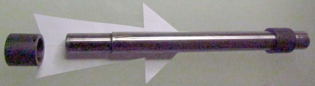
I got the machined torlon bearings back. My TheSamba contact reviewed them and thought they were very well done.
I also began wirebrushing the transaxle case. It shines up nicely.
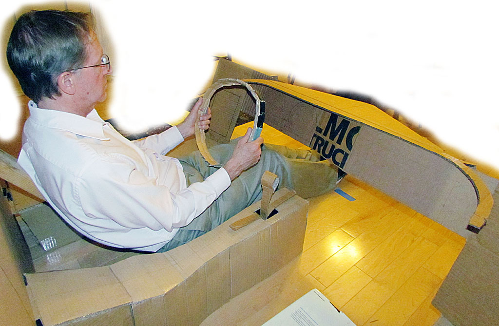
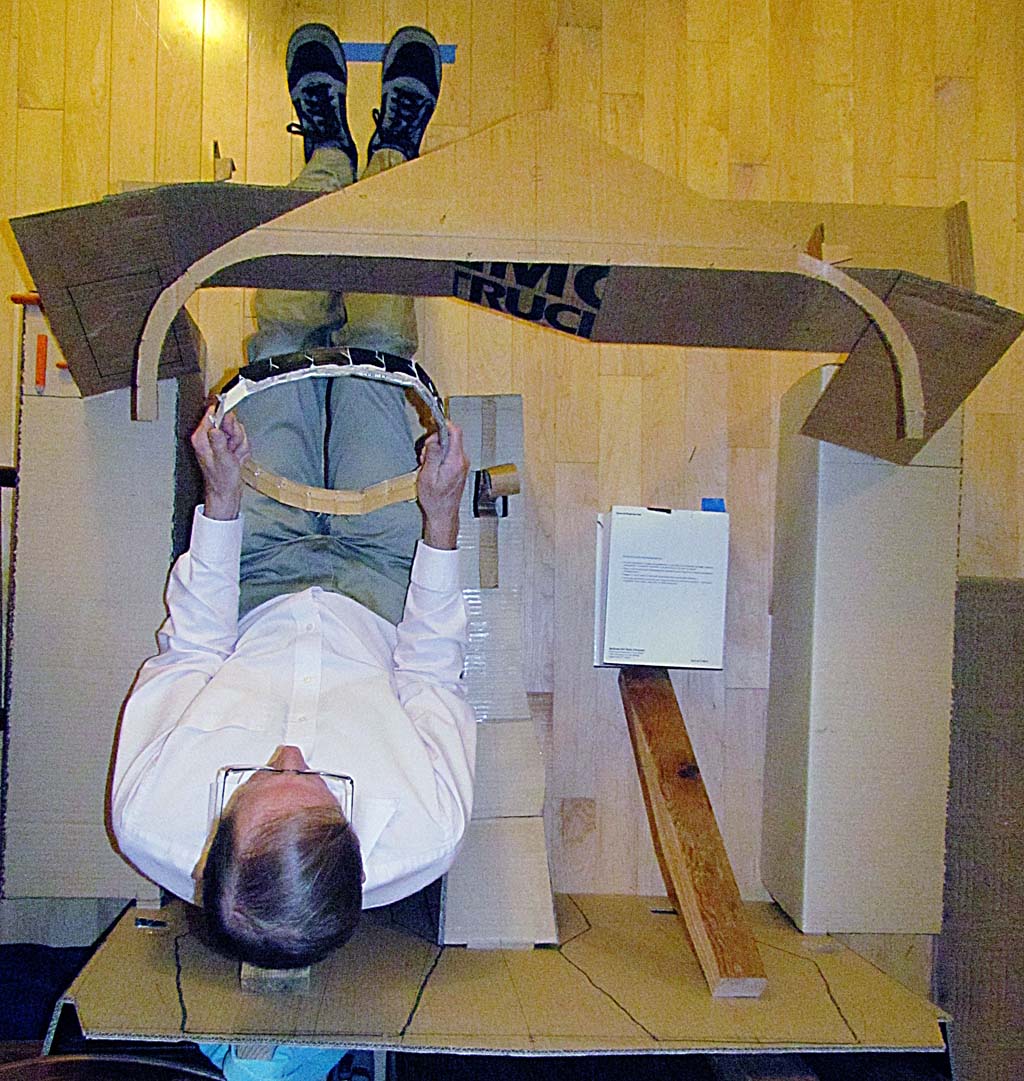
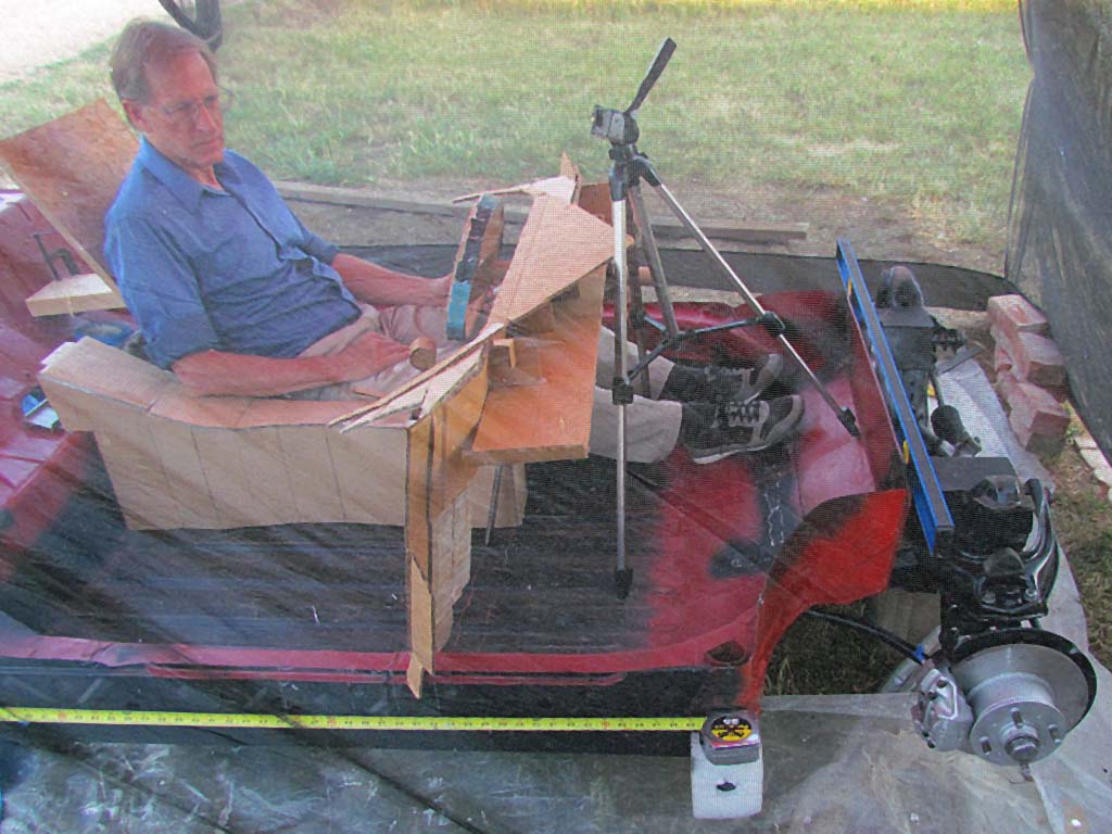
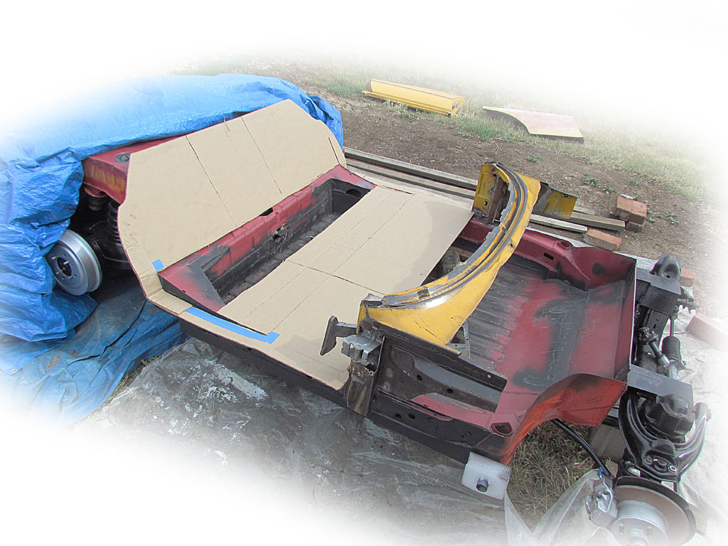
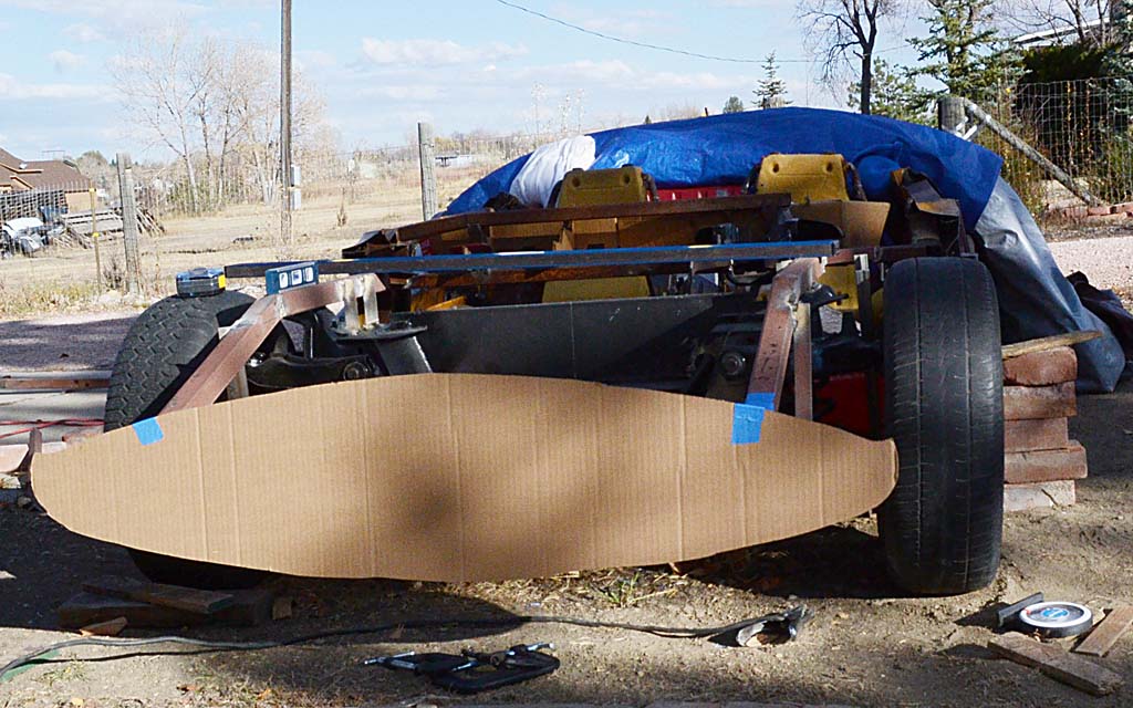
Taking my 3D file dimensions, I created a mockup of the interior out of corrugated cardboard.
Now I could really sit in it with another person and test the steering wheel and pedal distances.
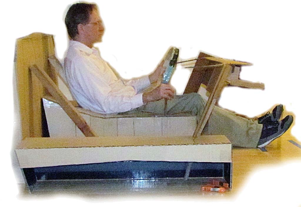
One thing is very obvious - it is hard to slide into.
I think the steering will have to tilt up as much as it can, as well as telescope.
Because the seats were made to remain fixed, the pedals will need to adjust, too.
And I am not sure what to do about the safety brake.
On the 412, it was behind the gearshift, which will put it inside the center console.
Maybe that will still work.
Looking ahead, I am hoping the original vehicle returns to the Heritage Center so I can visit it and take some confirming dimensions.
But until then, the weather is warming and I can put brakes and wheels on the chassis and begin welding on the other mechanicals.
APRIL 2
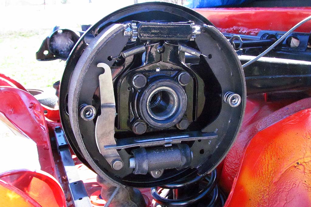
Cleaned up, assembled, and mounted the rear brakes.
They will never look this good again.
MARCH 27-APRIL 10
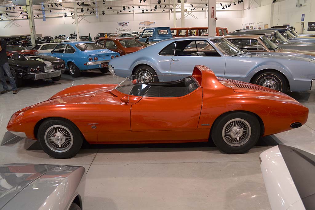
The Monza SS has returned to the GM Heritage Center.
I made an appointment to visit the Center to better document the car.
I will be permitted to take measurements IF... I do not touch the car.
I am developing a technique of casting light onto it to create visual landmarks and then photograph it from multiple angles.
My first two tests on the Chevy Jr go-kart body works.
I found an owner of a red Corvette who allowed me to use my technique on his car in his garage.
The garage is well lit and the car is very red.
The experiment points out the need for a better light source.
With only five days before leaving for Detroit, I locate the light I want and it arrives the day before I leave.
No time to do another test - I just hope it will all work as planned.
APRIL 18 - THE REAL ARTICLE
I asked my son to go along with me and he was happy to and able to take the time off.
We drove, so on the way we visited Frank Lloyd Wright's Robie House in Chicago.
On Monday morning, we showed up promptly for our appointment and visited the real article at the General Motors Heritage Center in Sterling, Michigan.
It is located a couple of miles north of the GM Technical Center.
The staff were very personable and helpful in getting us set up, and we were allowed to be in the Center all day.
It seemed like enough time, but it was not.
After waiting over 50 years, I was a little overwhelmed by the reality of it, and exhausted by the preparations to get there.
I now know better what I would need to really do what I want, but still, we accomplished all my basics goals.
I think I have enough to be able to accurately recreate the body.
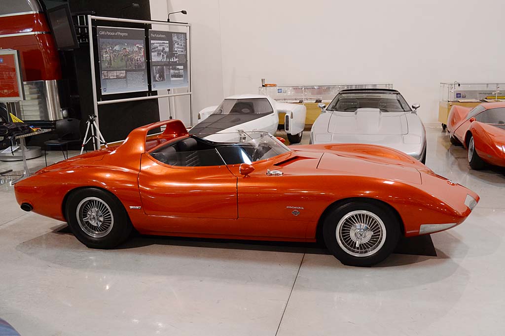
What was it like? Well... Two first impressions:
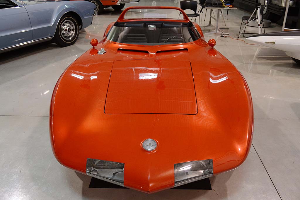
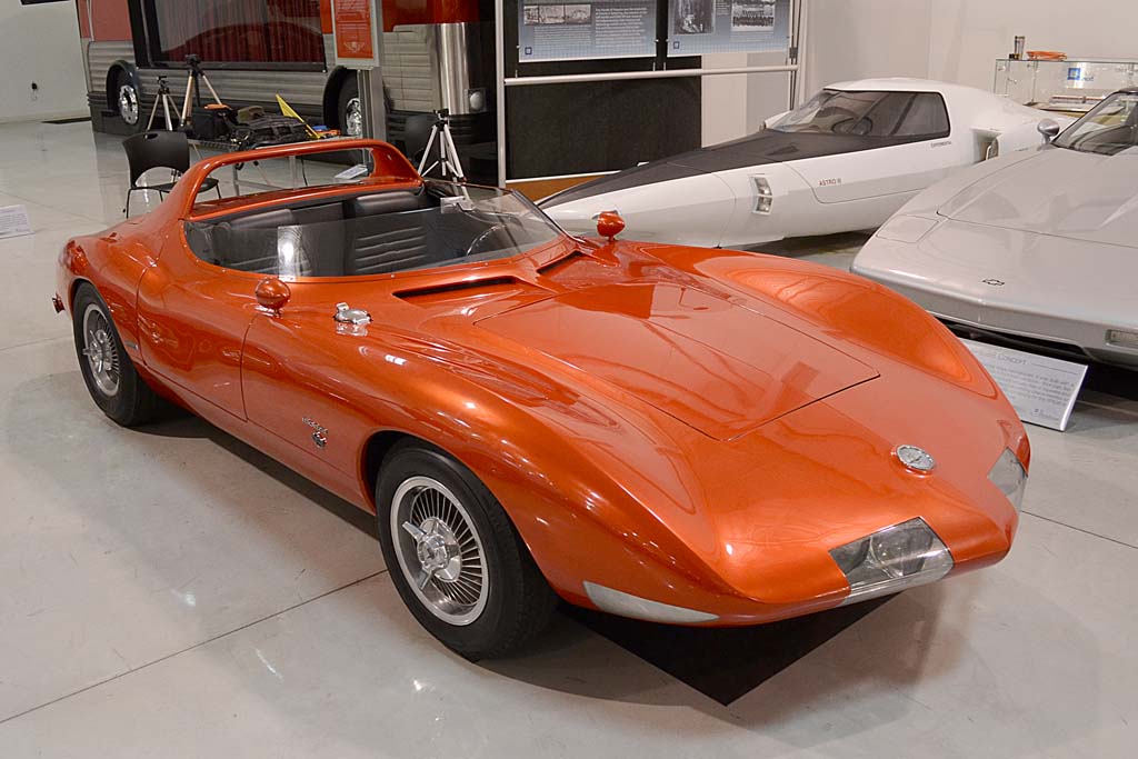
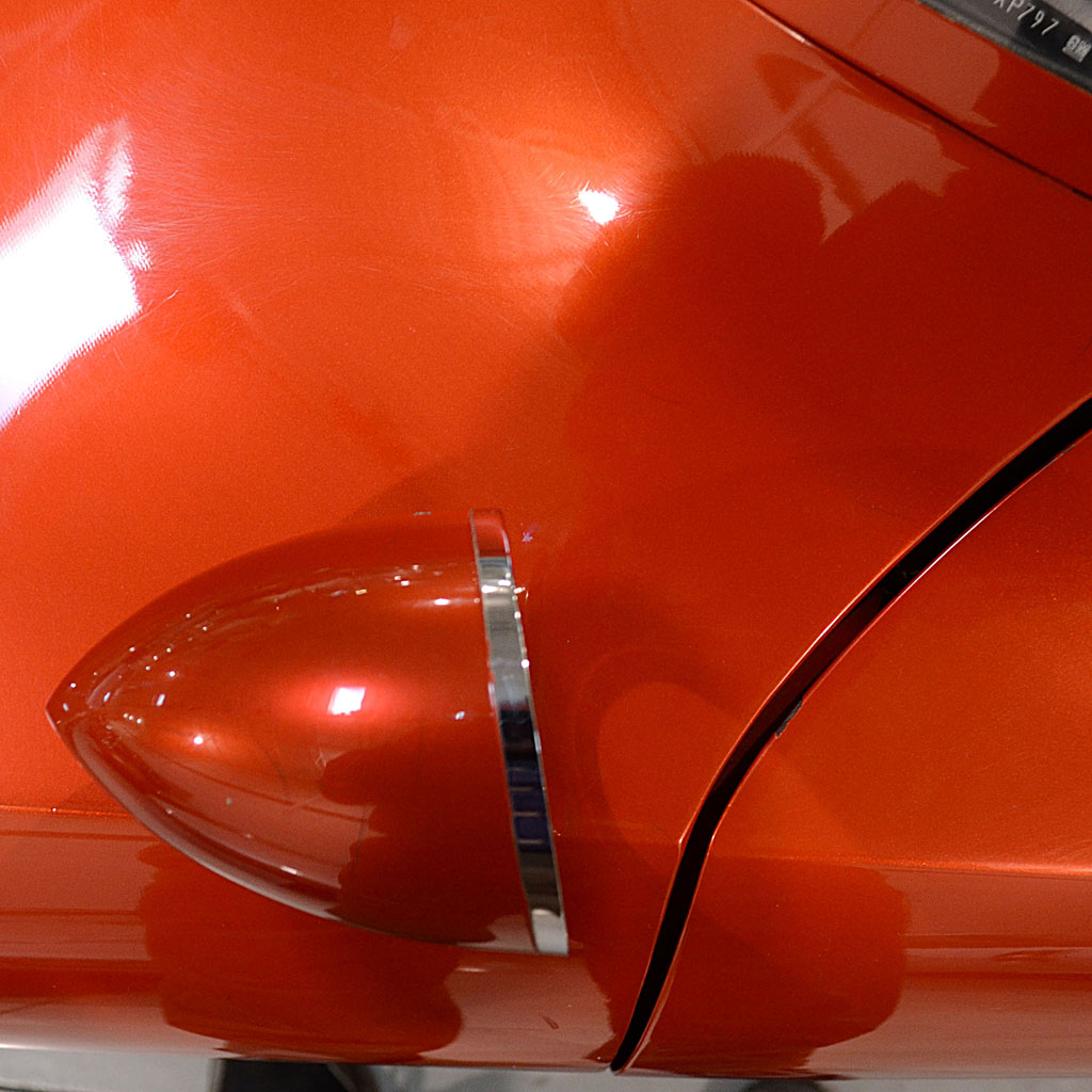
1) The car is painted a red metallic - but unlike any shade of red metallic I have ever seen.
And the color changes shade of red depending on the angle.
And the highlight is a gold glow. I have a new puzzle to solve now.
I have since learned that it is a tri-color, so it is similar to a candy, but more involved depending on how each coat was formulated.
GM had their own way of painting tri-colors on their concept cars.
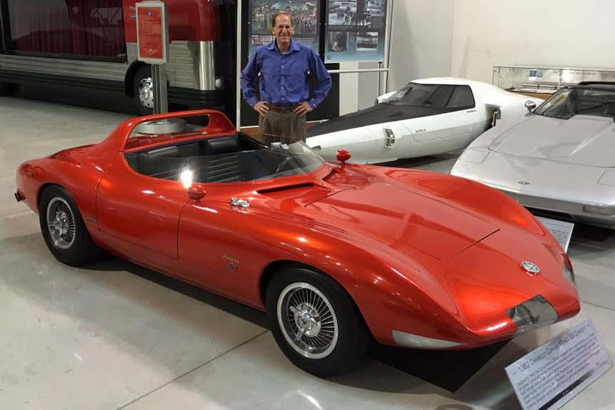
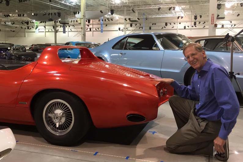
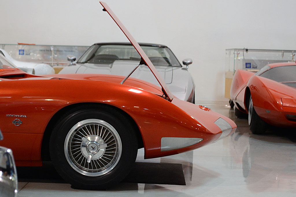
2) The length and width did not surprise me - it was what I had learned to expect.
But the height was truly low! My hand in the photo is at the level of the upper lip of the rear cove (and no, I am not touching it!)
It appears my cockpit mockup is pretty accurate. And it appears to be difficult for the driver to get into.
Some things I learned:
* The paint color has been the same for as long as anyone there remembers.
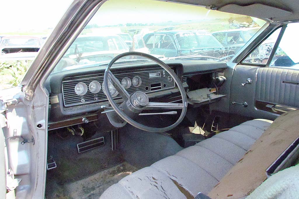
* The steering wheel does move in and out, but does not detach, like what I have seen for the GT.
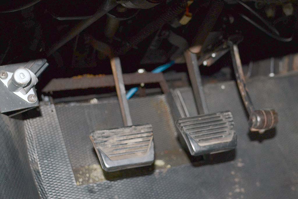
* The pedals (note the roller for the accellerator) did adjust since the seat did not, were electrically operated, but work no longer.
* The interior has no heater - just outside air vented and controllable inside.
* There are indeed two gas tanks, one in each fender behind the front wheels, with a crossover, and totalling about 9-1/2 gallons.
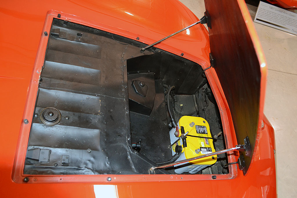
* The front trunk space is nearly totally useless. Half of it is boxed in to the top of the compartment.
The front half is exposed to whatever comes in underneath the front end, and is not large enough for a standard spare.
It is completely unobstructed to the nose and one can access the headlights. The battery is also located in front.
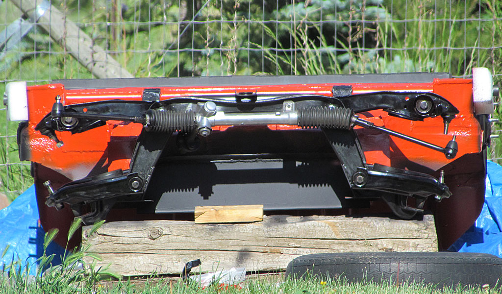
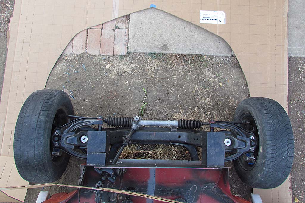
* The wheelbase measures 88 inches right on. The averaged measured front track of 54.5 inches is close to the reported spec of 53.5 inches.
* The suspension uses wishbones and torsion bars on all four corners.
* The two Weber-style three-barrel, one-piece carburators were just rebuilt.
It was very hard to have to walk away. No one was trying to hurry us out, but there was an event in there that evening.
Finally, I had to turn my back and walk out to the lobby and say my thanks-yous and goodbyes.
And my day with the car was over.
APRIL 20
We visited Chicago the next day, going through the Musuem of Science and Technology, which is a worthy experience.
We walked along the lake and suppered on deep-dish pizza and on the next day, visited with Mel Francis.
APRIL 21
Mel has already traveled the route I am going down, so I wanted to meet him and admire his workmanship and just connect on a kindred level.
His interpretation of the Monza resulted in a larger, mechanically improved vehicle that retains the look and character of the car.
And it is, quite simply stated, beautifully made! The surface finish looked better than the real thing.
He offered to coach me as I progress. Since mine will be a more literal interpretation, I look forward to parking them side by side some day.
And with that visit, our trip ended and we drove straight home.
MAY
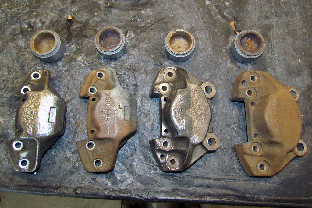
After taking some time away to complete another project, I began taking apart the front disk brakes from the Manta front end.
The one-way bolts holding the caliper halves together had to be drilled out, but the pistons popped out at 100 psi and looked clean and without corrosion on the sliding surfaces.
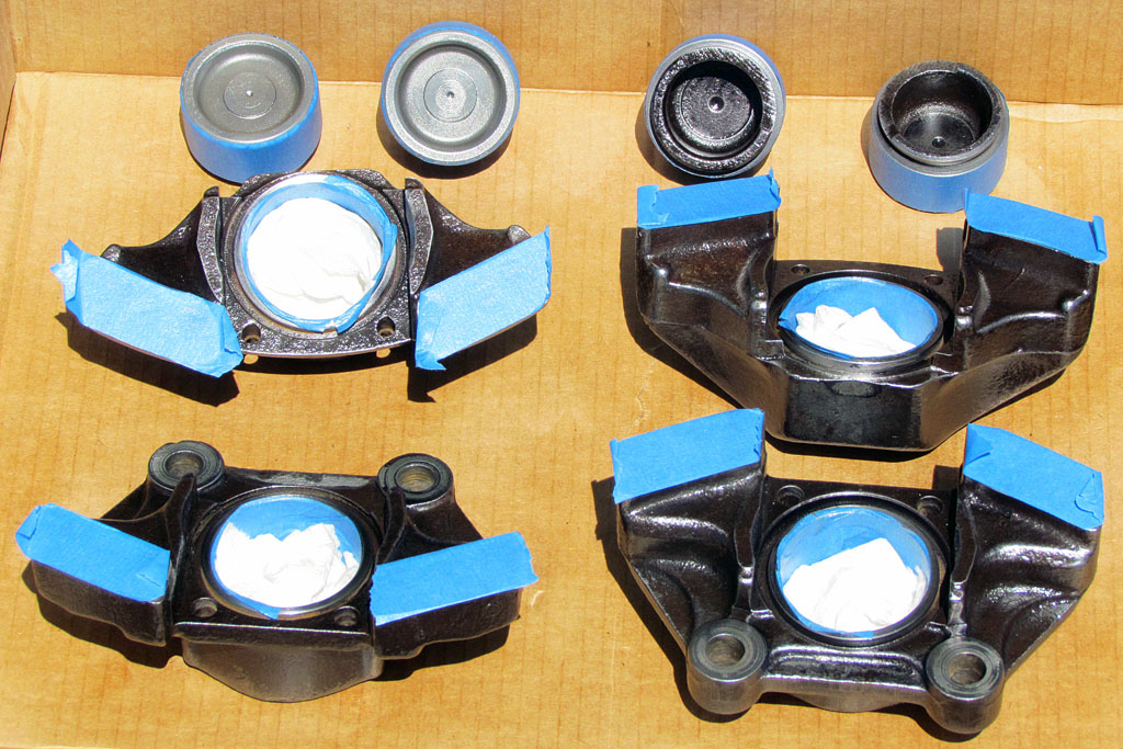
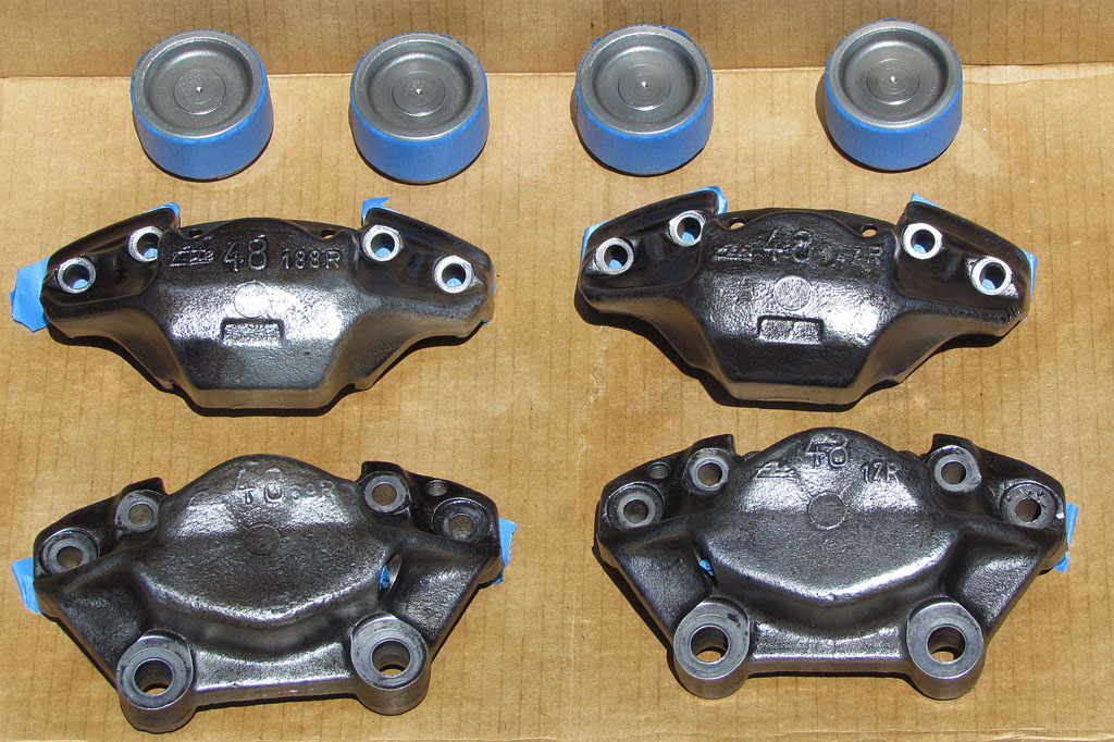
More wire-brushing and clean-up and new paint and new hoses and they are ready to reassemble.
MAY 24
I checked in with the man who is polishing my wheels.
It was taking more effort than he expected, so we talked alternatives.
What he will do is soda blast the wheels and just polish out the outward facing surfaces.
Looks like they will really pop.
MAY 28-JUNE 4
The weather in May was cold and wet and because this is still an outdoor project, nothing got done on the chassis.
But Memorial weekend was warm and sunny and I could pull off the tarp and begin to assemble the front end.
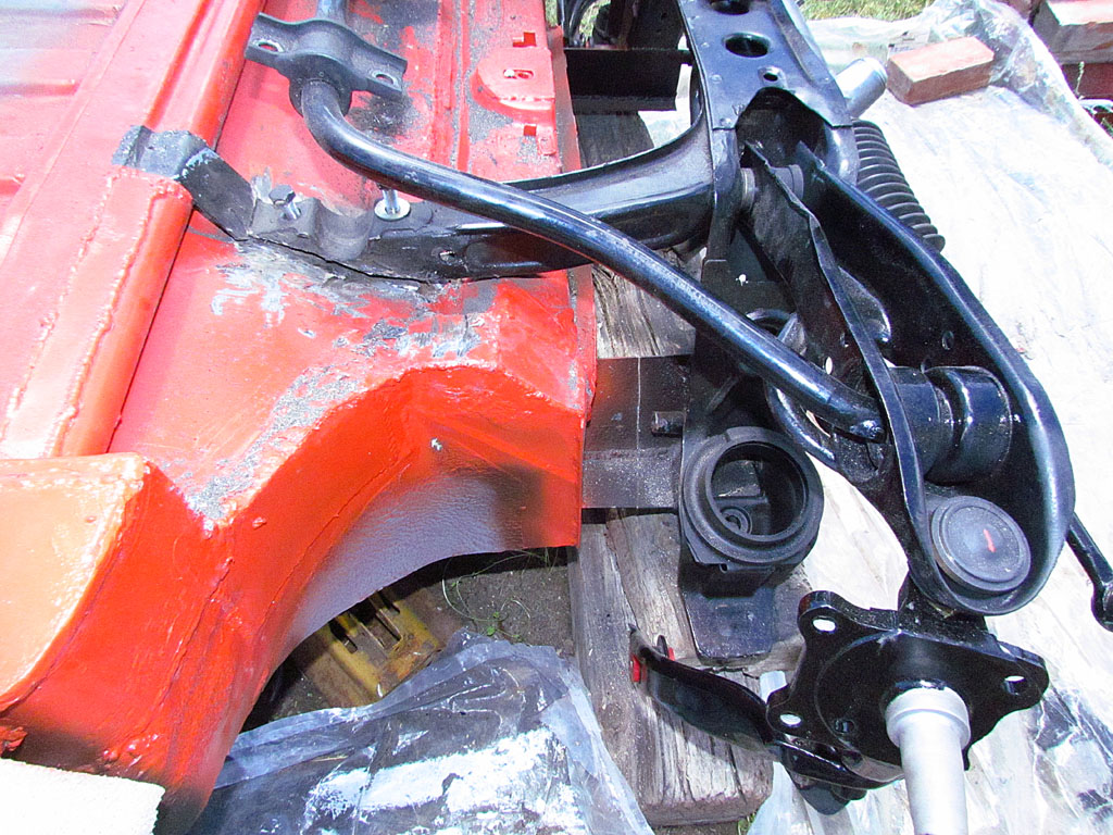
It involved some problem-solving, but I got the upper and lower control arms on and the anti-sway bar.
Only I goofed and on my last try, fitted it on effectively upside down.
Now normally, there is no upside-down because from the chassis mounting points, it does not matter.
But... the rubber+metal mounting plates, which have to be worked onto the bar from the ends, do not have the same height mounting surface.
They were already on the bar and now only one side of each plate could mount flush to its chassis contact point.
It took 3/8 inches of washers to meet the other mounting point. I think it's solid.
It was at this point that a problem became evident... the front end was not the same height left and right.
What was more, after leveling and measuring, the wheelbase was off left to right as well. By 1/2 in both cases.
So - the hard decision was made to cut free the driver side front end and reset it and weld it back together.
We did and it worked and looked that way it should.
Reassembly continured. Because the chassis is upside down right now,
I was having a time trying to orient the spindles and brake shields and steering connectors - which tickled my neighbor's funny bone.
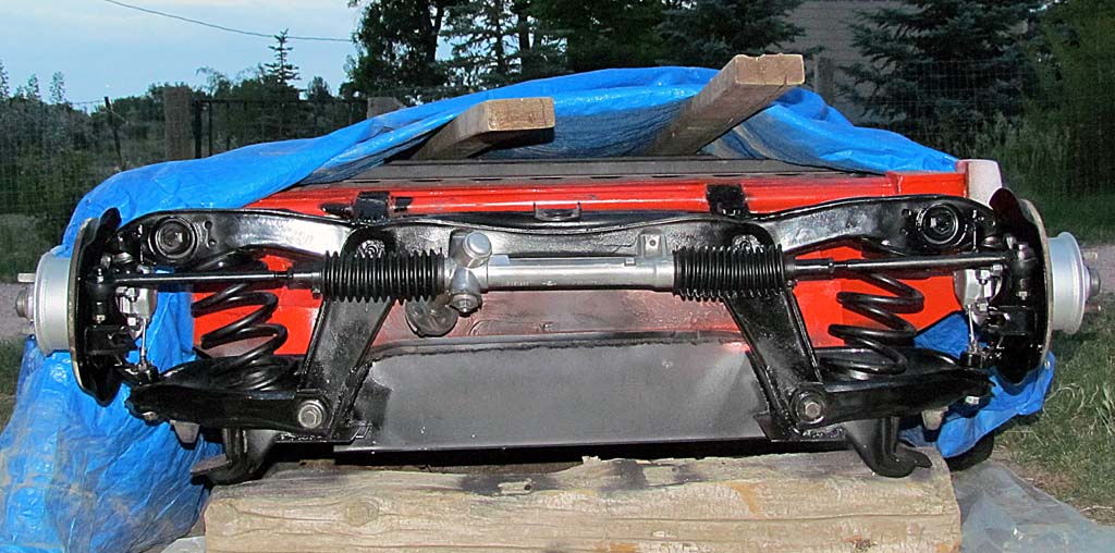
The last hurdle was the springs. Honestly, I do not know how I got them out while it was all assembled.
They would not go back in now. I could not compress them enough.
After much internet searching I learned they were supposed to have a spring rate of 140 ppi, which means the preloading was mighty high.
Being unable to accurately decide what I needed for coilovers, I decided to stay with springs and shocks.
If it works, I have saved a bunch of money, but it not, I will have to buy them anyway.
I did not need all that spring now since there was no engine to support.
I calculated the front will weigh about the same as a Beetle or a Karman Ghia (about 600 lbs or 300/wheel),
so I would only need about two inches of preloading. So I cut them down.
If I am wrong, I will know more exactly what I need. So there!
Still left to do: shocks, rotors, and calipers.
JUNE
The last couple months or so, I have been corresponding with a retired GM designer who is very knowledgeable about GM in the 1960s.
In conjunction with that, I have been doing a bunch of internet research and beginning to make other contacts with people associated with the Monza.
There are not many around. Shinoda and Lapine are both dead now. I want to talk with those who have some living memory of those times.
The one designer and I are trying to nail down the history of both the body and its variations as well as the chassis.
There is more than one storyline to sort out, but we seem to be nailing it down piece by piece and date by date.
I am now planning on publishing a monograph on the Monza and its sibling, the GT, and its cousin, the Astro 1.
The Astro 1 is related by the chassis development history, in case you were wondering.
Oh... and the color of the original?!?! Not the color it wears now! More on all that at some later time.
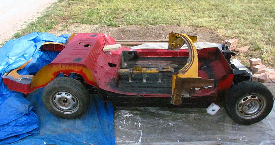
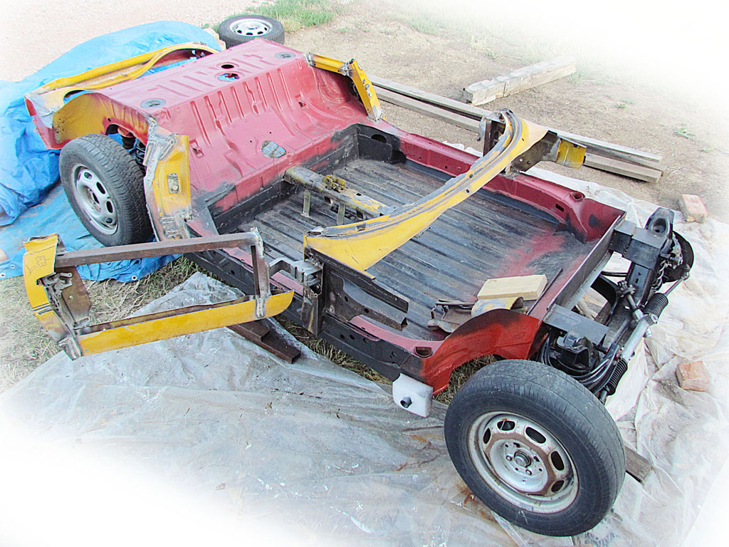
The weather is hot and clear and I can get time out of doors.
My neighbor and I flip over the chassis (it came down with a solid thud) and attempt to weigh it.
We get 250 lbs for the rear and 130 for the front, but then we realize we measured wrongly.
We needed to use the wheels as the fulcrum point; instead we still pivoted off the underside supports which are not in the same place.
So my guess is it is less than 450 lbs and mayber more like 350 including the brakes.
I spend a weekend measuring from the rear wheel centers and from the chassis point that represents the door bottom cut line.
I measure left side and right side separately and the center line, then use a laser level to throw a line across the pan from side to side and mark that onto the pan.
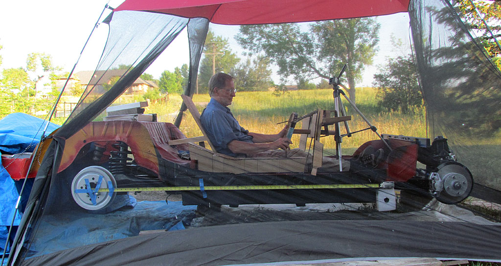
Because of the heat, I put up a screened tent over the car to work under.
My neighbor thinks it looks like a Flintstone-mobile.
I then set up the interior mockup I made earlier and try it out.
I discover my suspicion about the footwell is true. I don't have enough foot room.
Shifting the seat back two inches - as much as I can and still keep the rear bulkhead position behind the doors - gives me just enough room.
I decide that I will no longer make the pedals adjustable. I am a 50 percentile man, so my link measurements are about average.
If someone is taller than I am, they probably won't be able to drive it. If someone is shorter, they can use a cushion.
That will simplify things. But I WILL need that steering wheel to shift out of the way.
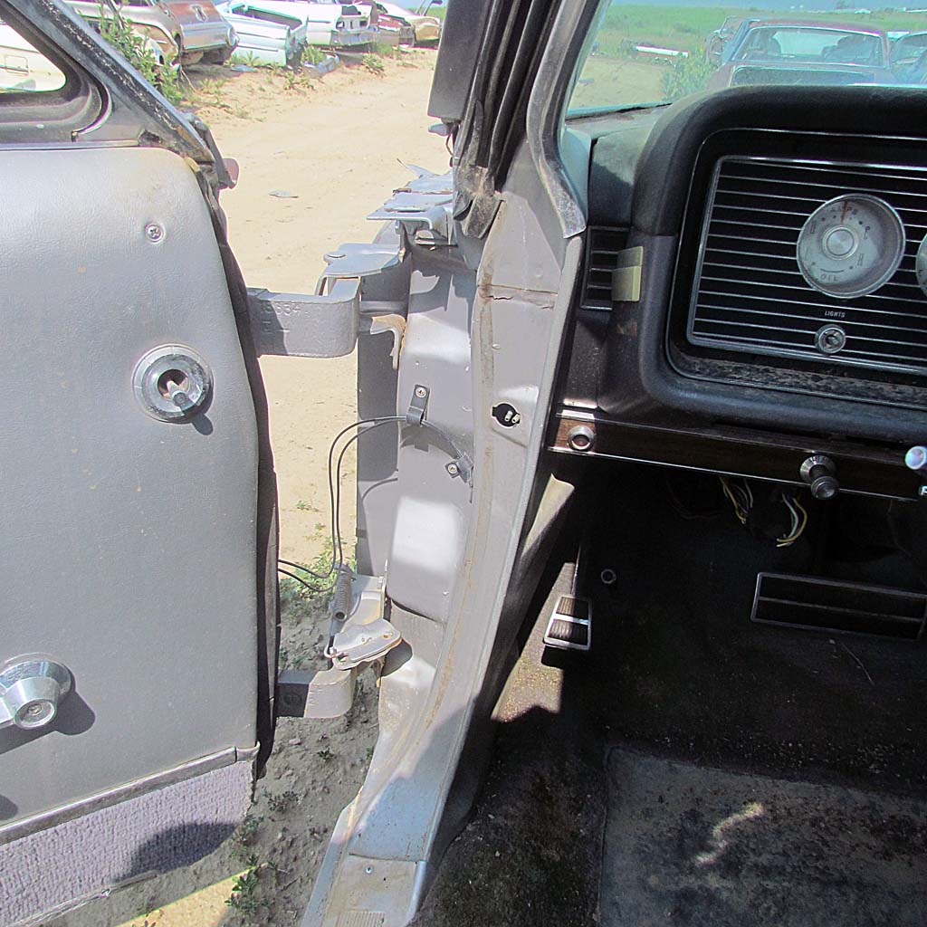
So my neighbor and I visit the local salvage yard. We talked alot about door hinges.
I want hinges that allow the door to open away from the body so I don't have to engineer the panels for them to cut into the body when opening.
We locate a 66 Mercury without a front end. It is perfect to access and remove the hinges, which are in good shape.
What's more, it has a tilt-up steering column without all the stalks and airbag of a modern movable column.
I also found an instrument cluster to an 84 Rabbit GTI. I am hoping the tach works. Mine stopped a couple of years ago.
I swap it out, but the tach STILL does not work. Maybe it's the wire from the coil?
Back home, I cut down the VW 412 door post/windshield member to fit onto the chassis.
It is still the same width of the chassis, so the windshield frame will tie the door posts together and hold their angle.
The following weekend, we begin to add the hinges... wellllll, only one hinge.
It takes some cutting and adjusting to make it work. The hinges are so big and strong, we decide we only need one per door.
There is not much space on the post to fit two, anyway.
By the end of the day, though, it is two steps forward and one step back.
I realize that SOMEHOW - I don't know how I did it - somehow the driver side door post is an inch and an eighth ahead of the passenger side!
AAARRGH!!!! Seeing my angst, my neighbor is sympathic instead of ribbing me about my mistake.
Nothing left to do but cut that post out and reweld it before going on.
JULY 3-4
It's a long weekend ahead and I am hopeful about what can be accomplished.
First off of course is repositioning the driver-side doorpost.
I insist my neighbor and I BOTH measure and agree on the same location for the post.
We do and get the post set and weld away, followed by putting on the hinge.
It takes most of a morning.
That afternoon we begin to set the rear door post. It is a bit of a kluge.
I use a cardboard cutout of the body outline to make sure the post is inside the contour.
Then it is cut and weld and cut and fit and cut and weld some more.
I needed to remember that the door cut line is NOT the same as the door sill line, which should be an inch or more in.
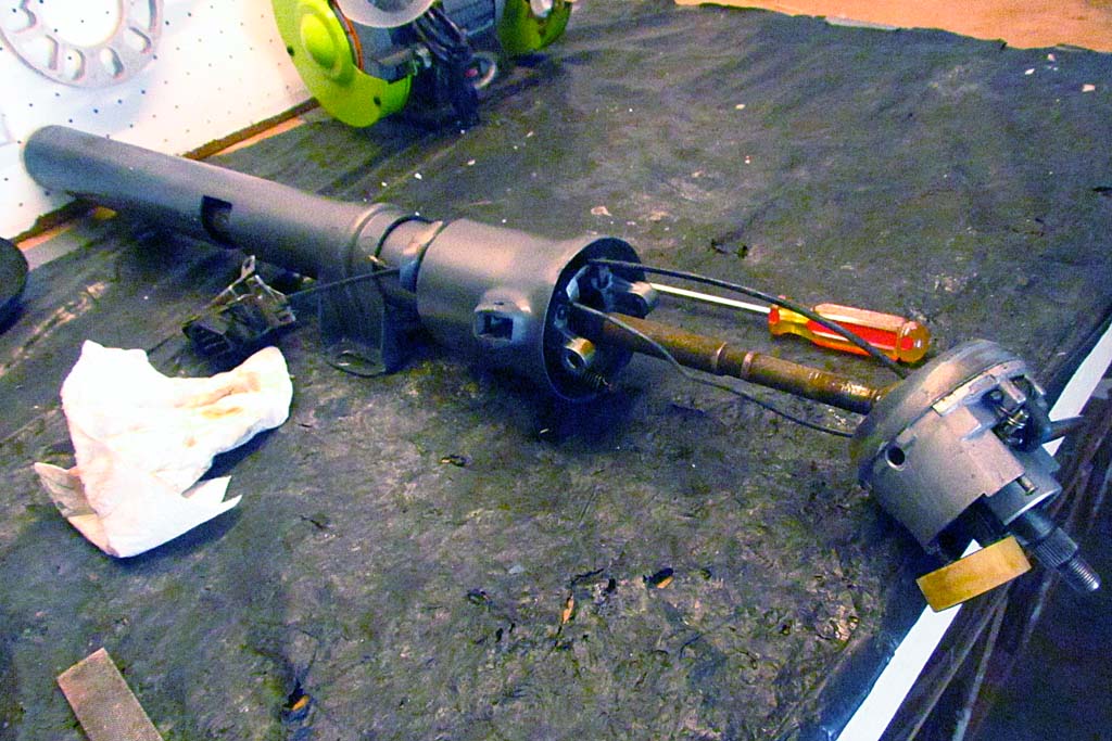
In between all this (and over three days), I take the steering column apart little by little.
But we are stumped. We cannot figure out how to separate the hinge collar from the shifter collar.
We cannot make out any more bolts to remove.
So much for the first day.
The next day we cut up the other 412 door post based on what we learned the day before and get it positioned and welded in place.
By midafternoon, after dodging showers in the afternoon, we discuss how best to make the door frame.
The end plate which has the latch mechanism will definitely be used.
But to use the rest of the door becomes more and more work to make happen.
The hinges are different and nonadjustable. The front plate is actually a double walled box.
There would need to be multiple cuts to get the pieces needed, and then to be welded back togheter.
Finally it becomes evident that the best way is to start fresh and use some clean, strong pieces of channel and square tubing to simply, easily, and strongly make the frame.
And so we do. Actually, we did use the bottom plate from the 412 door in order to take advantage of its shape for where the door meets the sill.
It welds up quickly enough, but because of a loose joint in the single door hinge, it needs to be shortened 1/4 inch to prevent the door from dropping when opened.
When all is said and done, it opens and shuts with a nice ker-chunk.
One door done! The next one soon follows.
REST OF JULY
The rest of the month goes by and I am stymied about how to take apart the tilt column.
Eventually, in desperation, I undo two springs that tension the tiltable component the steering wheel eventually attaches to,
and sure enough, it all comes apart. Putting it back may not be so easy when getting those springs back on.
I also use my drawings to mock up the dash+wrap-around over the doors, and the bulkhead behind the seats.
Actually, I use the outside of it in order to define the outside edge.
It requires a lot more measuring to establish datum lines on the chassis.
I also make one more trip to Martin's Salvage to bring home a set of 1995 Camaro headlights.
I settle on those rather than more modern HIDs because of their size, and also because of cost.
They will fit in the top half of the original clamshell headlight doors.
That means I only need to drop down the top leaf, hinging it at the nose line.
It also means I will be very close to the minimum headlight height.
Enough I hope to pass the State Patrol inspection when the car is inspected for titling.
It took a lot of unscrewing just to get to all the attachments screws for the headlight assembly.
I had to remove the nose piece and the inner wheel wells to finally get them all.
AUGUST
This was the month to work out the seating. We also had our first grandchild this month!
Working again from my drawings, I recreated in mockup form the position, angles, and general dimensions of the Monza SS seats.
I was concern about their 45 degree seatback angle being too much, but it turned out that it was actually very comfortable!
Then I had to decide - would I make static seats with no adjustment, or try to fit adjustable ones?
I could make the immovable ones to look just like the originals, but it would only work for me.
I already made the pedals non-adjustable. But can I trim down the Celica (see Oct. '14) seats enough to fit??
The bolsters are too big and the seatbacks are rather wide, too. And can I get them low enough?!?!
SEPTEMBER 4-17
Well... I did already have those Celica seats and they are adjustable and it would be preferable if they could fit.
So, I pulled off the covers and removed the seatback side foam pieces, revealing the frame.
Using blocks, I worked at setting up the seat to get the angle and rake I wanted.
And it worked out! I guess I will use them!!
So I take them apart to clean them up. There was a LOT of hair in the mechanism!
The next step is to fabricate mounts for the seats. Bring out the cutoff wheel and welder!
OCTOBER 2-16
By Oct. 2, the mounts are in and the seats are on.
The shifter goes in next. The shift rod and stick shift are shortened (10" and 8" respectively).
Doing the final alignment of the shift rod reveals that the driver's seat is a smidge too close to it.
The seat will not go all the way back. One could live with this.
The seat is centered nicely on the steering column, but it spoils the benefit of the moveable seat.
By moving the seat all the way back and bringing the seatback into a straight upright position,
there is significantly more space in front of the seat to step into the car. And THAT is important!
It is difficult enough already to swing the legs in when seated.
With the seat back and a couple of grab handles, one can step in and let oneself down into the seat.
I am now as far from 30 as when I was when I was born, so that is a practical consideration for me.
So the rear mounting points will have to be repositioned leftward 3/4".
That modification gets done November 15 and, viola, it works nicely.
OCTOBER 17 - NOVEMBER 13
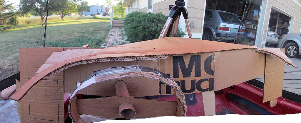
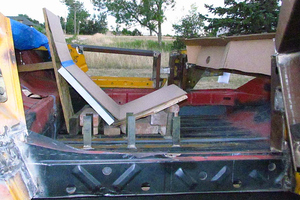
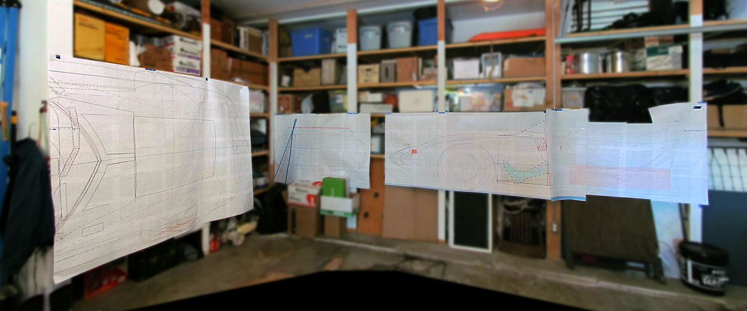
With the seats taken care of, it is time to move forward. To do so, I will need an accurate outline of the nose clip.
To have that, I decide to define it using contours from my drawings.
It takes a long two weeks of my spare time to print up full-sized drawings, transfer them to cardboard sheets,
cut out the sheets, and assemble them into a single module.
I actually create a negative cavity defined by the outline of the sheets so I can place in over the front end and see what fits - or doesn't fit.
Once done, it takes about an hour of consultation and checking measurements with my neighbor to decide how to proceed.
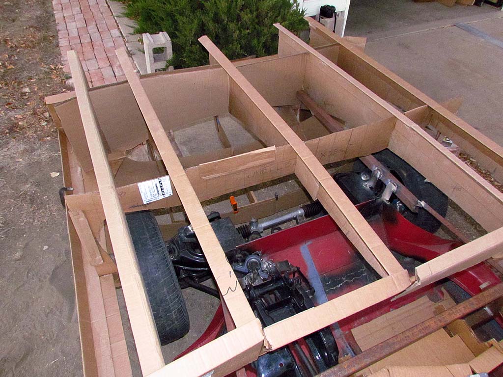
By November 13, we have the first frame members in place up to the headlight/hood hinge points.
Boxing it in, doing the hinges and headlights, and working the wheel wells come next.
And we have made provision for the gas tanks in the area behind the front wheel wells.
My goal is to get the transaxle completed and install it and the engine before the end of the year.
The weather has been wonderful, but the cold and snow are closing in and I want to move this into the garage to work on over the winter.
Check out 2017 for more progress!
The Build--2016
January - April

1st ROW
(L) Torlon bearings to replace the countershaft needle bearings. Make these and one does not need to make a new shaft. They cost more, but should wear better and longer.
(R) The fit and tolerances are snug. Interestingly, the countershaft is slightly thicker on one end, so the bearings must go on from the other.
2nd ROW
(L) Based on the Photomodeler drawings, here is the me sitting in a full-sized cardboard mockup of the interior.
(C) The side view. Note the near 30 degree angle of the seat! Getting in the real thing will require some gymnastics. The steering wheel is definitely in the way. But once seated, it seems to be comfortable, and not so tight side-by-side with a passenger. However, my shoulder will be right next to the door panel.
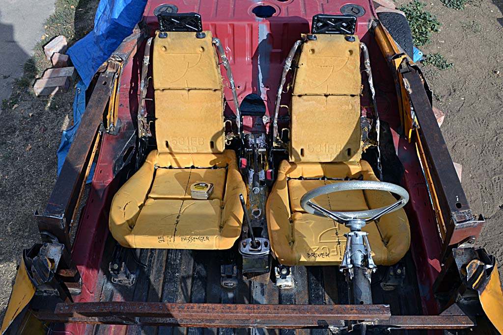
(R) Looking down on the layout
3rd ROW
(L) The rear brake cleaned up and with new parts
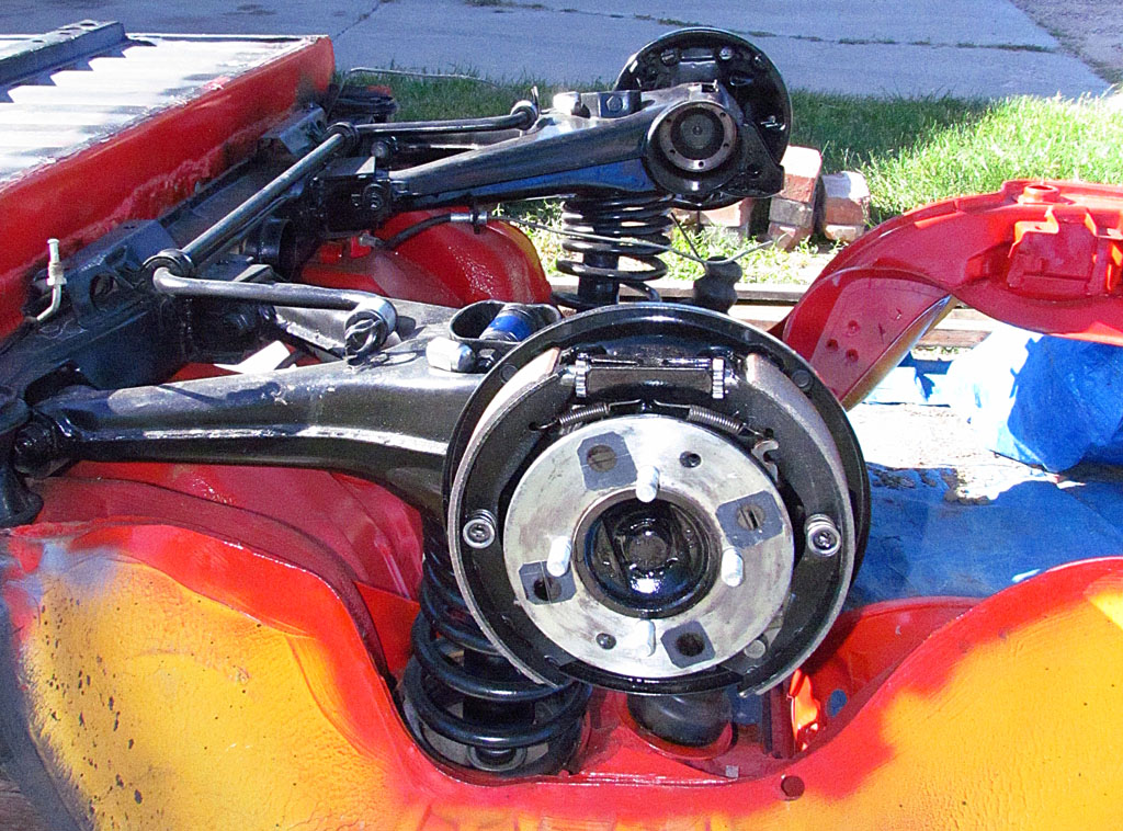
(C) And with the wheel shaft in place. Vince at Horizon drilled and inserted new lug bolts at the 110 mm spacing for the 13" wheels.
(R) Buttoned up with the new brake drums
Boy Meets Car

1st ROW
Meeting my 50 year old dream!
(L) First sight and first impressions
(C) I am really here!
(R) It's THIS LOW! (and, no, I'm not touching it.)
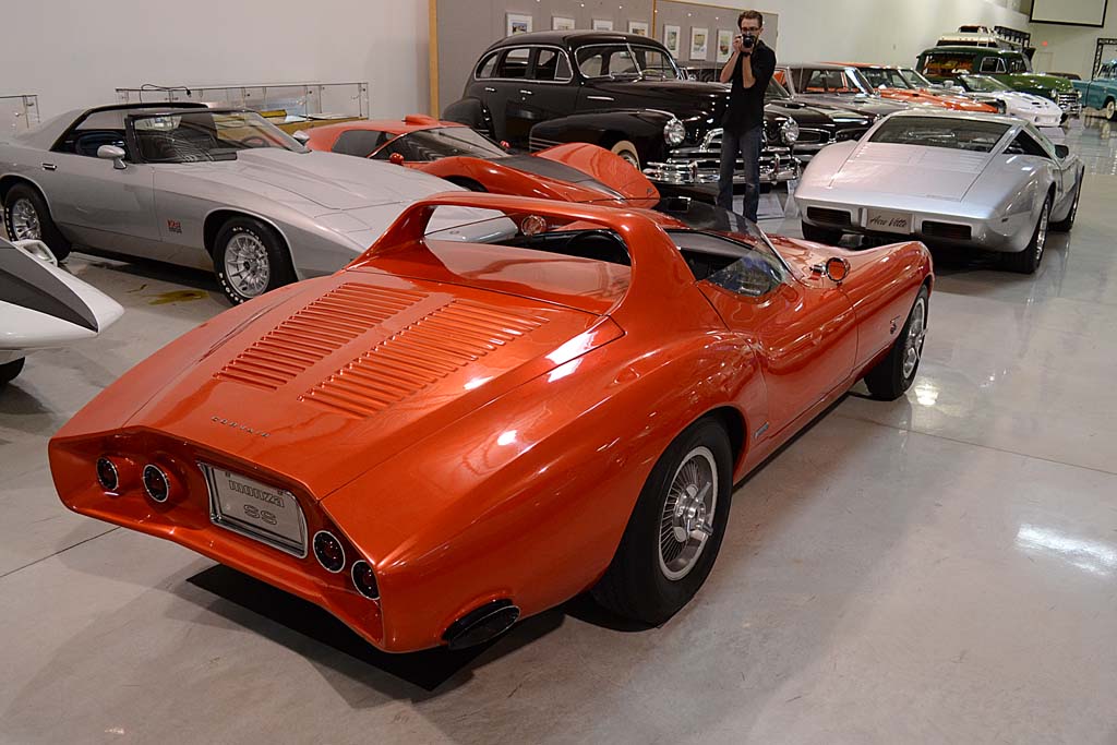
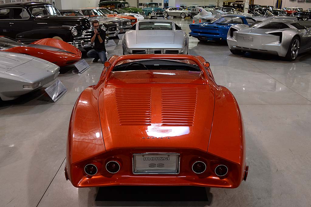
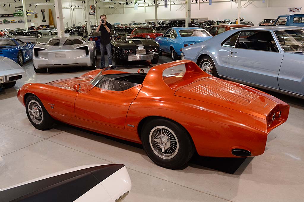
2nd-4th ROWS
The REAL ARTICLE!
Details


5th ROW
(L) WAHOO! Special permission!! A peak under the hood - I mean - trunk!!!
(C) This shows the hood propped open.
(R) The rear view mirror and paint close-up. This gives an idea how this custom candy-like color appears.
2nd ROW
(L) A hard-to-get shot of the pedals (without touching, and supervised!)
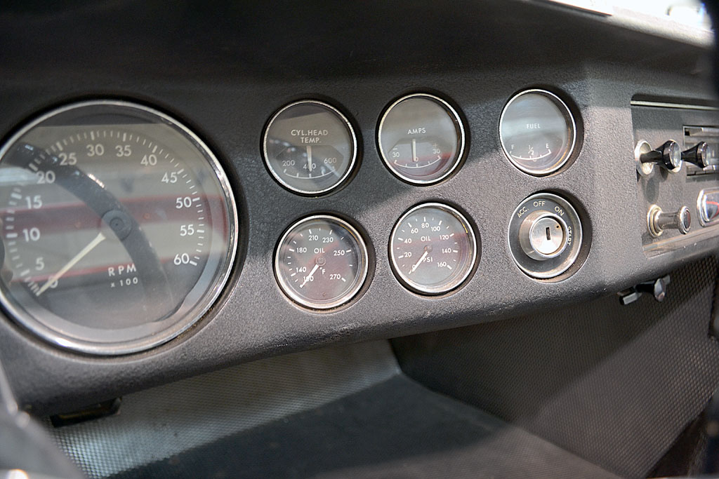
(C) The gauges to the right of the tach
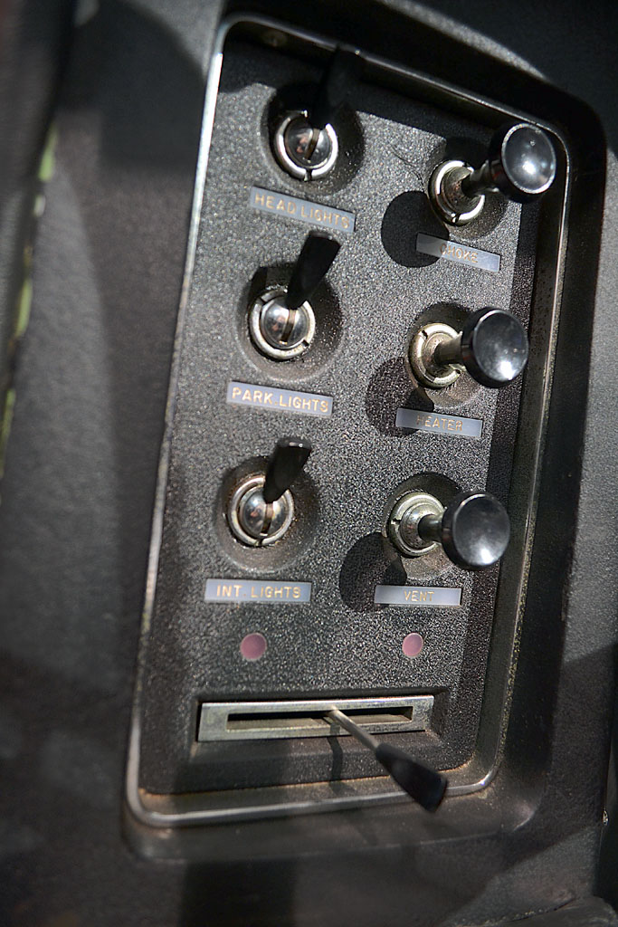
(R) Side panel to driver's left, by door (thanks to son's contortion ability)
3rd ROW
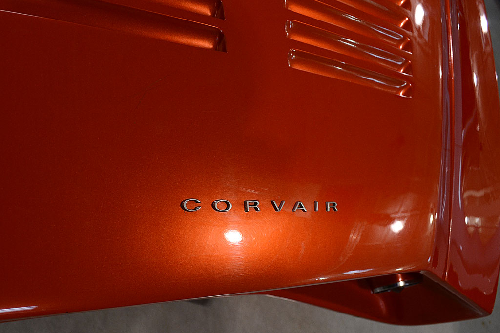
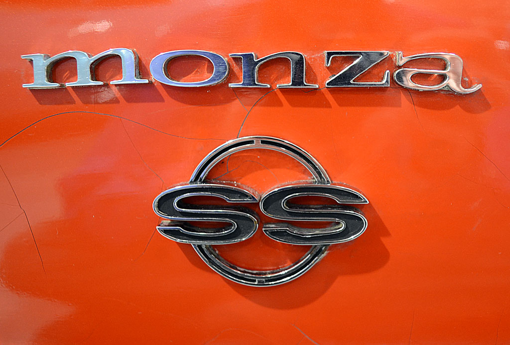
(L) The name letters are thinner than the production versions. Note also how the candy color-like glow appears.
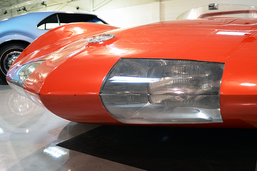
(C) The front Cibies. These were installed within a couple months of the car's NY Auto Show debut.
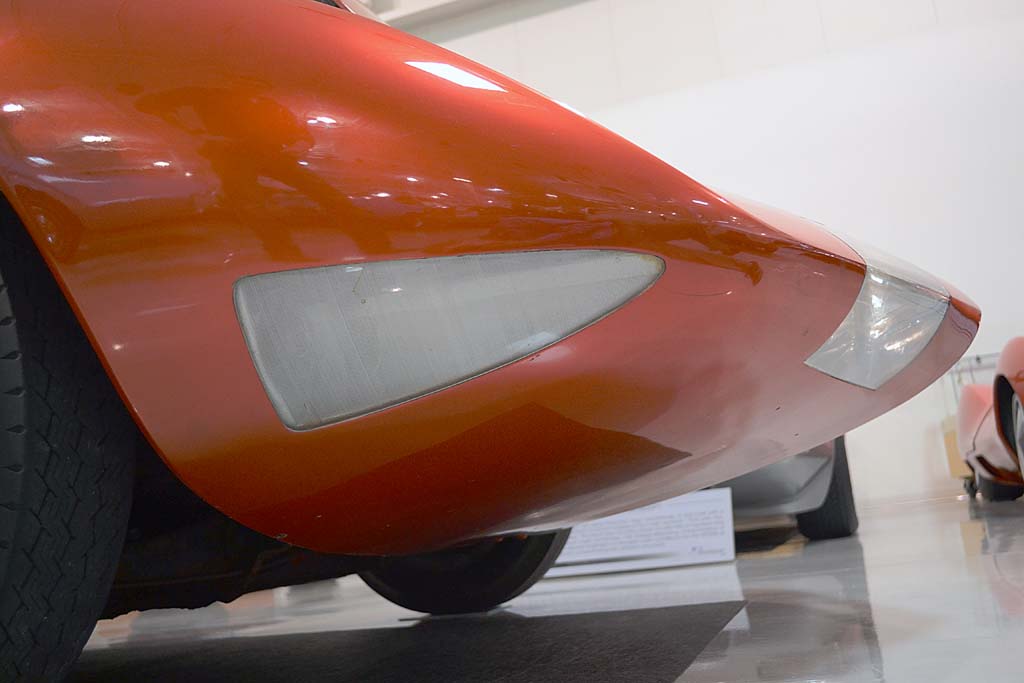
(R) The parking/running lights and nose bottom panel portion
4th ROW
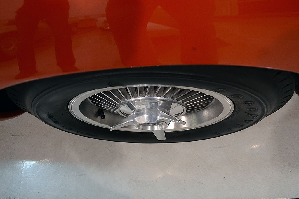
(L) This view of the wheel shows the amount of recess of the turbine spokes
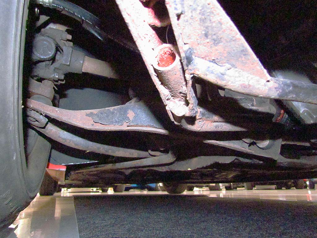
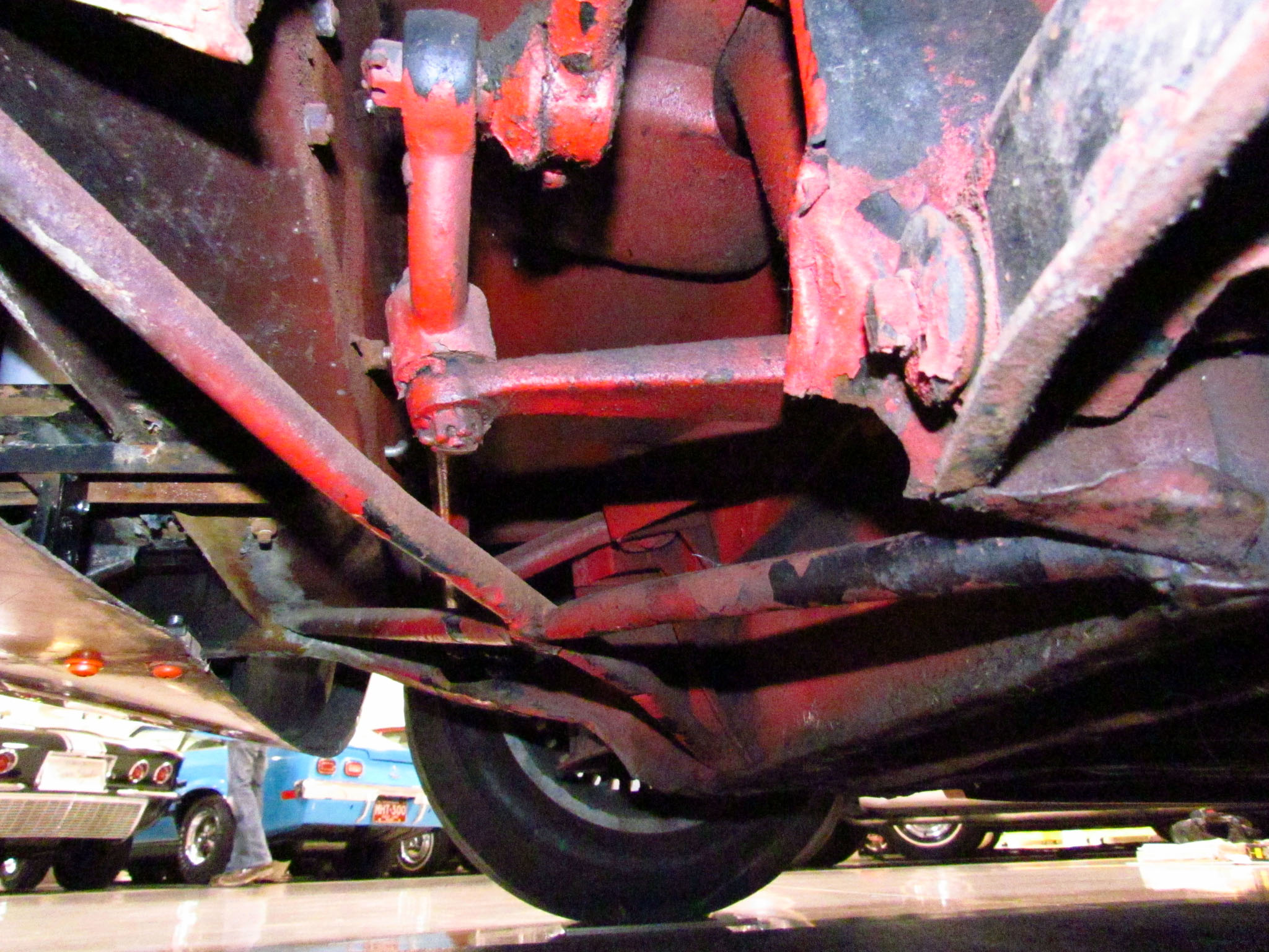
(C) The rear left suspensiion member. The rear torsion bar can be made out goint to the rocker panel.
(R) The underside in front of the front wheel. Note the openness into the nose cavity.
5th ROW
(L) The exhaust bell
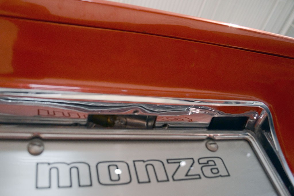
(C) The right dark rectangle is where one presses to open the hood latch.
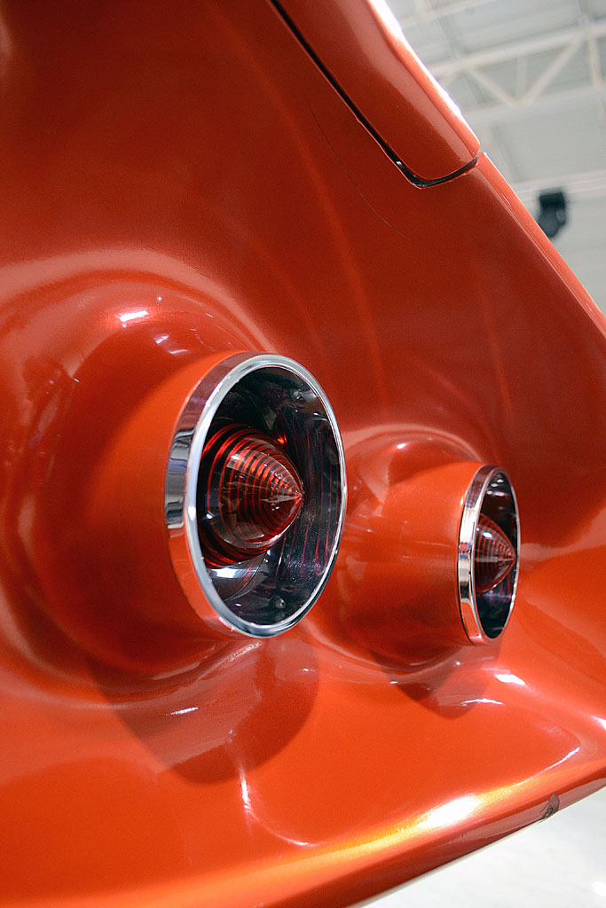
(R) Right side taillights
6th ROW
(L) Side emblem. Note the crazed paint
(C) Hood emblem
(R) Gas cap close-up
Monza SSR


1st ROW
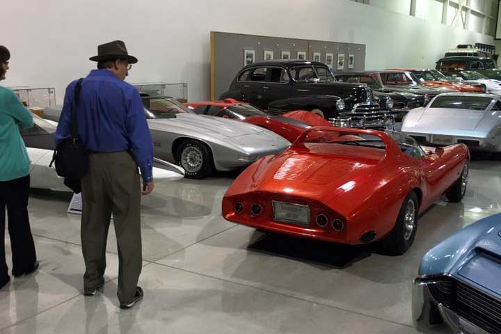
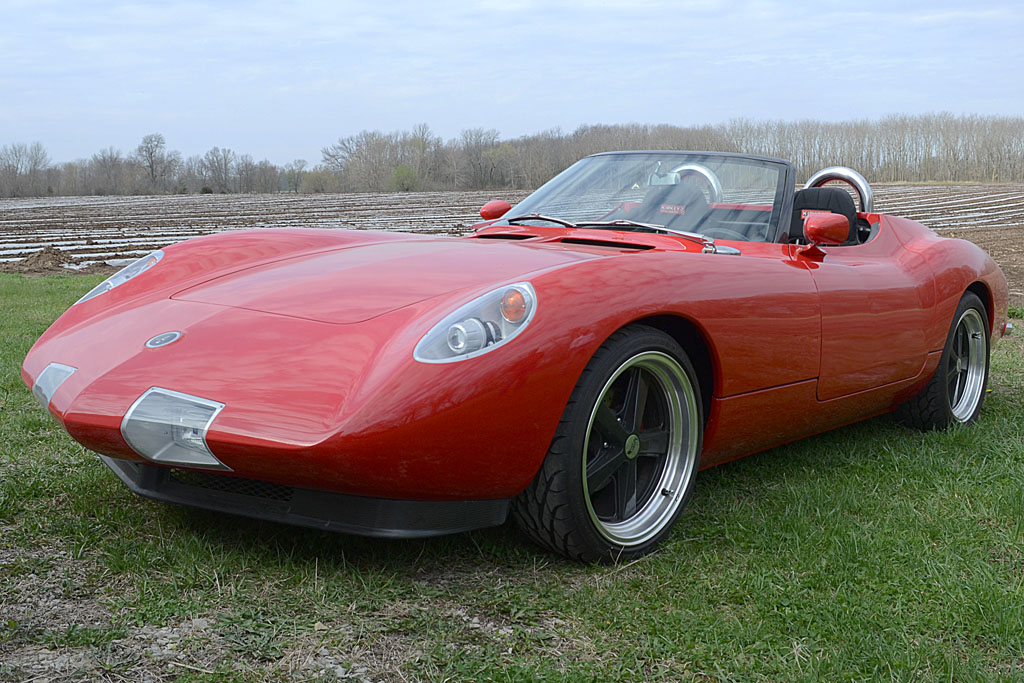
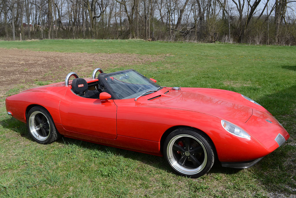
(L) Visiting Mel Francis' interpretation of the Monza SS
(M) Looks good with modern wheels
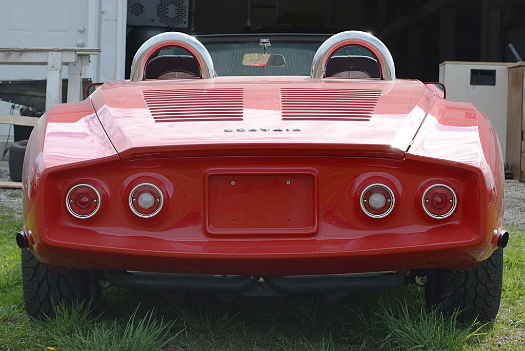
(R) Not your every day Corvair!
2nd ROW
(L) It's 106% larger than the original - built on a shortened production Gen2 Corvair chassis
(M) This one is updated to contemporary standards. Note the headrests, Momo steering wheel, and shift gate.
(R) Hey, Dad...can I borrow the keys?!
Front Disk Brake Rebuild


1st ROW
(L) The front disks - just beginning to wirebrush the outside
(C) And what the insides looked like
(R) Masked and coated with rust oxidizer
2nd ROW
(L) The outside coated
(C) Painted with brake silver paint and mounted
(R) Another view
June - July

1st ROW
(L) Anti-sway bar in place, but something's not right
(C) Cutting out the mounting point
(R) Back together and looking balanced
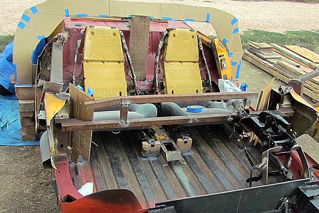
2nd ROW
(L) Driver test fit, using cardboard interior mockup
(C) Another view
(R) View from the driver's seat
3rd ROW
(L) VW 412 cut-down door posts in place
(C) Hinge donor vehicle
(R) Right hinge mounted
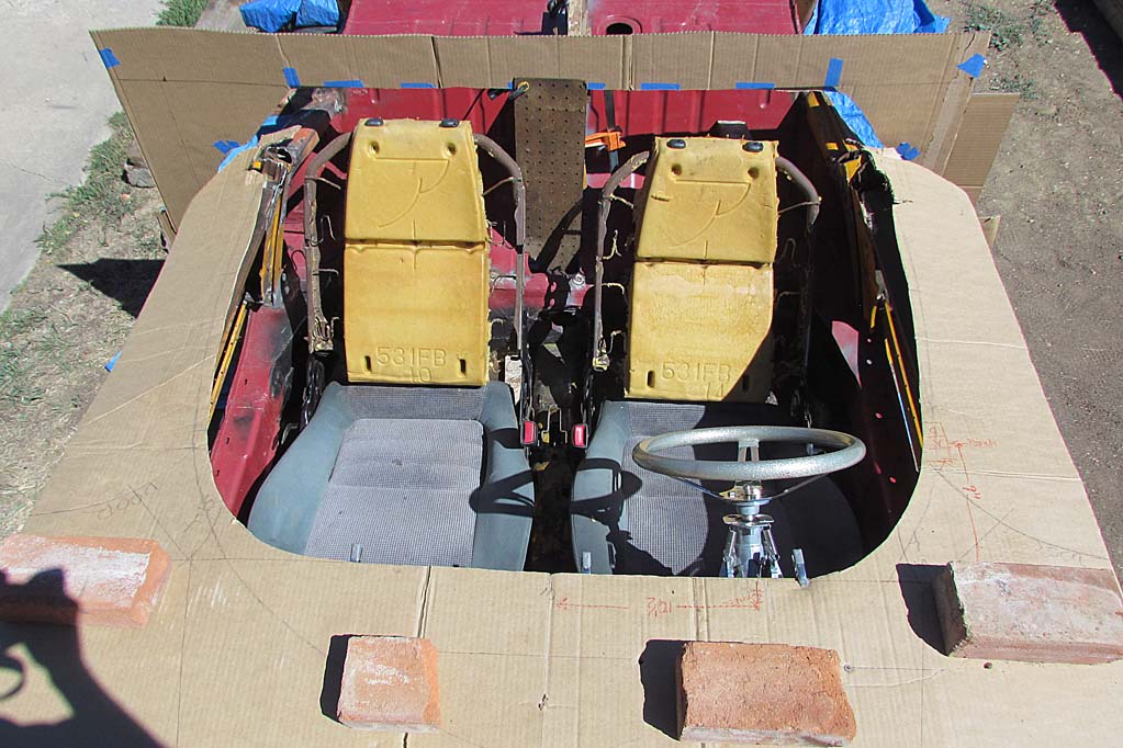
4th ROW
(L) Cardboard interior template showing width to outside of body and height behind driver.
(C) Side view of new door posts and door frame
(R) Overhead view showing door full open
July - October


1st ROW
(L) The tilt-up steering column in the '64 Mercury.
(C) Steering column partially disassambled. It only tilts 22 degrees - not quite enough.
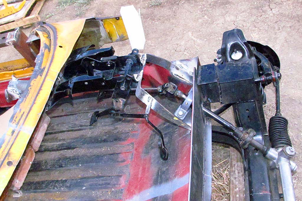
(R) Steering and pedal bracket installed
2nd ROW
(L) Establishing the seat position in rough mockup
(C) The dash panel is also mocked up and positioned.
(R) An overall view - the seatback angle is 45 degrees!
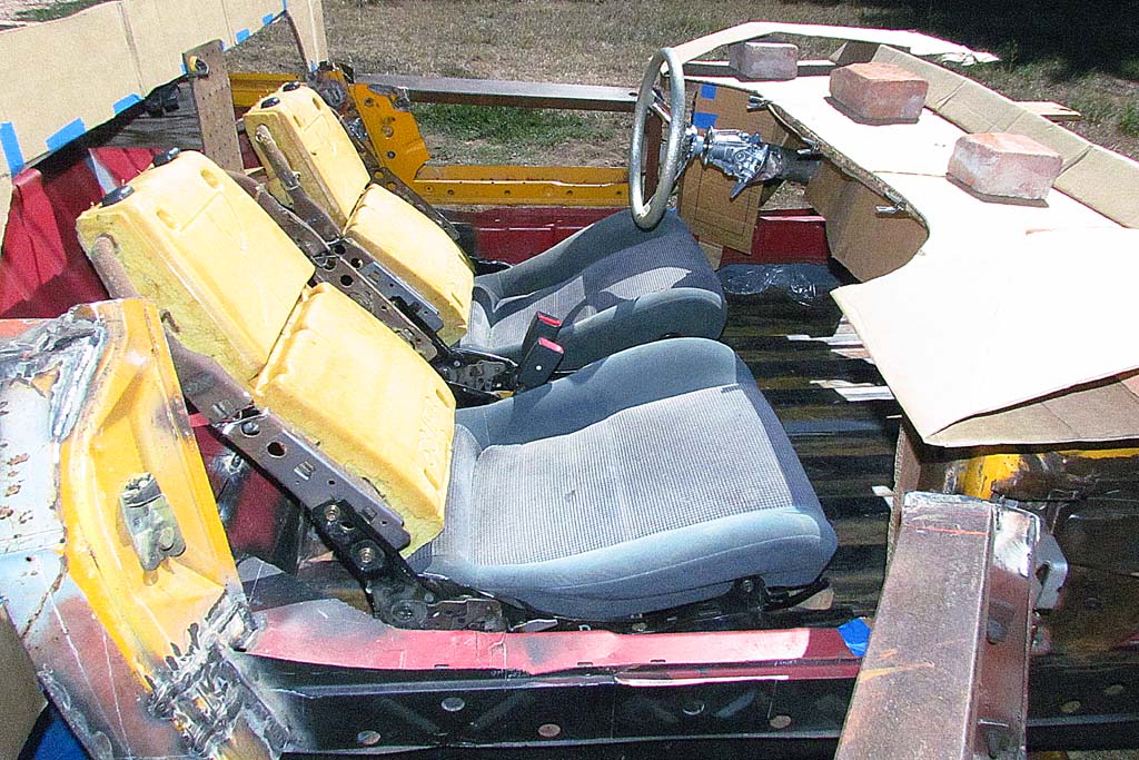
3rd ROW
(L) Trying out adjustable Celica seats
(C) The full-tilt seat back angle is just about right.
(R) And they fit, although tightly squeezing the center console.
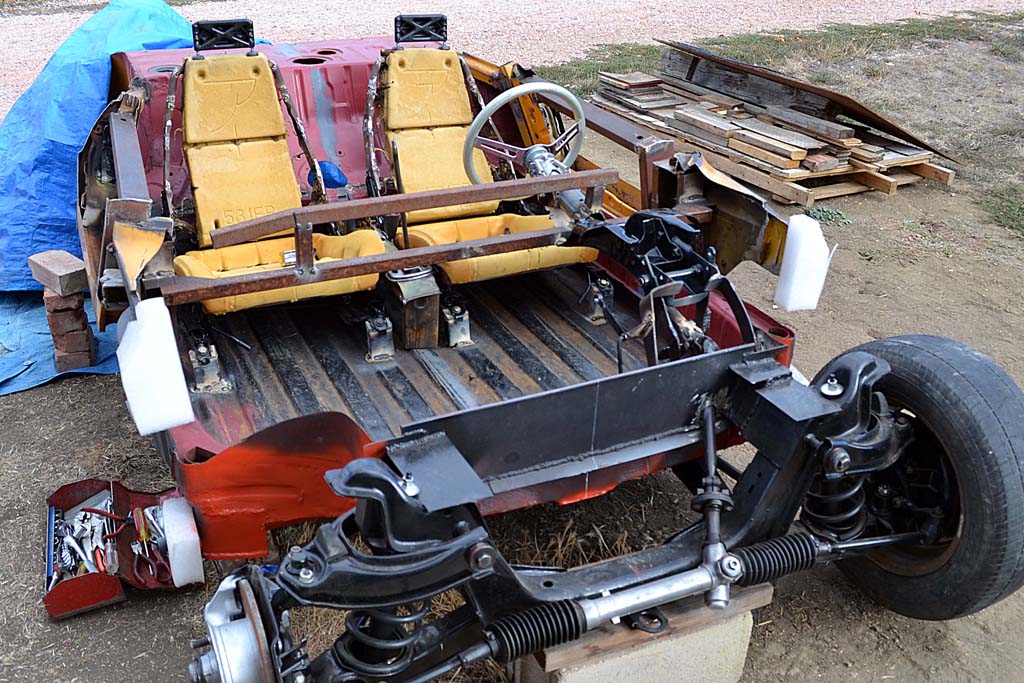
4th ROW
(L) The seats are now bolted in place. To help the fit and give the seatbacks the same shape as those on the Monza...
(C) ...the seatback frames were cut and welded to be narrower at the top.
Note the tilt steering mechanism. It's for a boat. It tilts up 45 degrees!
(R) Pedals, steering, seats, and shifter all in place. Its got the feel!
5th ROW
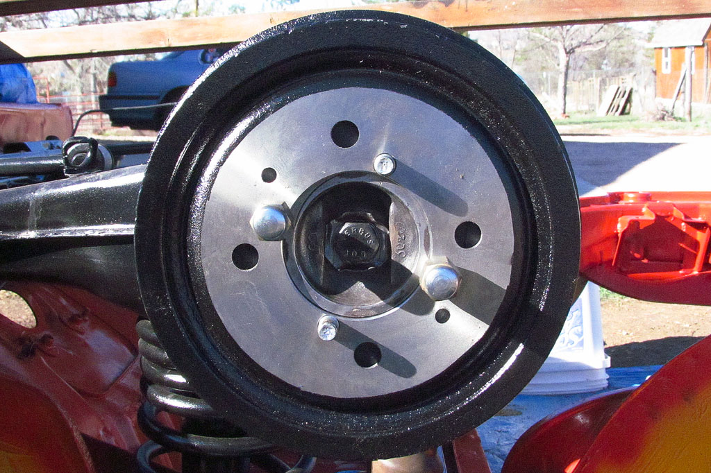
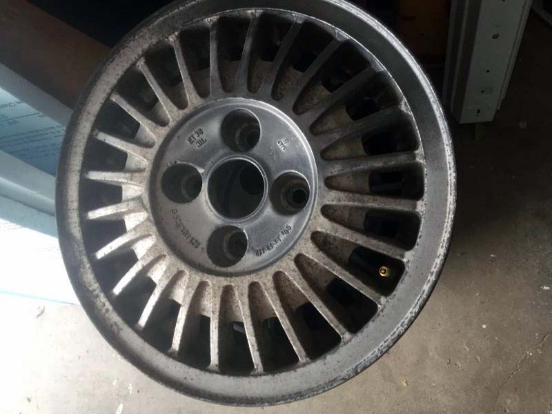
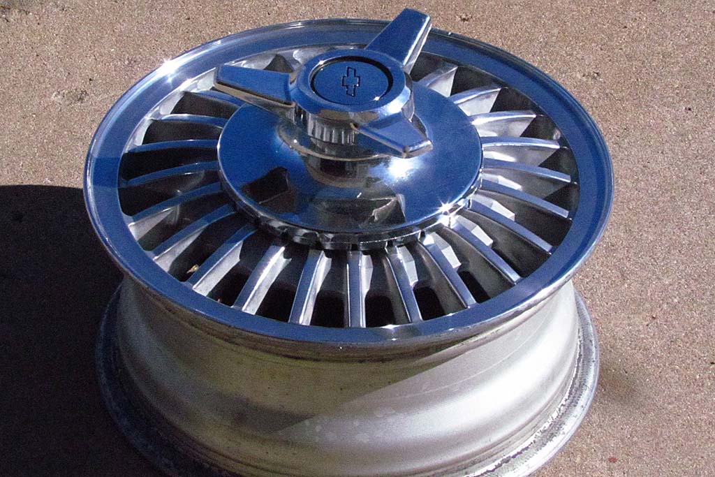
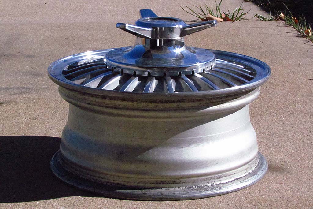
(L) At long last, the wheels came back and they are gorgeous! This is what I gave him...
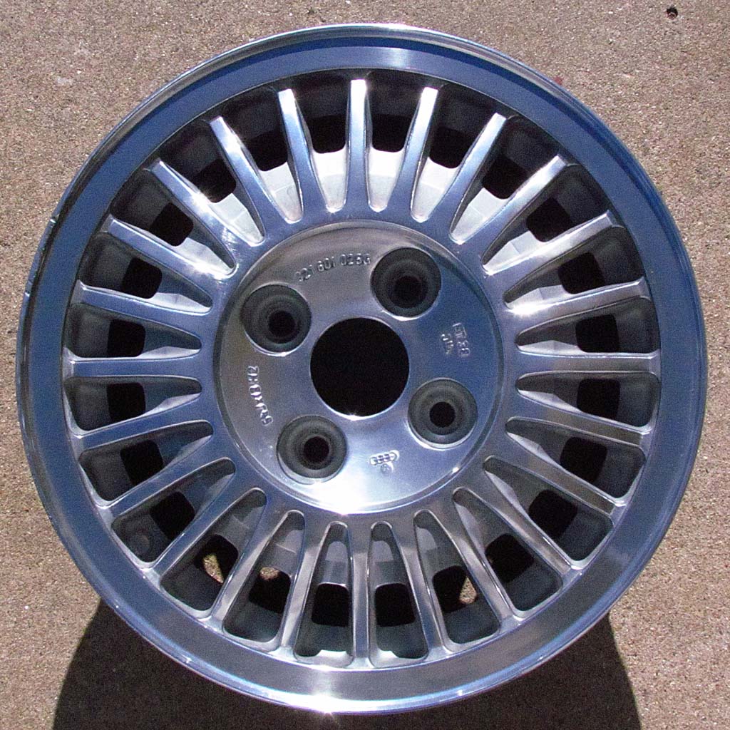
(C) ...and THIS is what I got back!
(R) I placed the center spinner from a Corvair wire wheel hubcap on it.
6th ROW
(L) It looks like a good approximation of the knock-off spinner mag wheels on the Monza.
(C) But... it sticks out waaaay too much. Shades of James Bond's DB5!
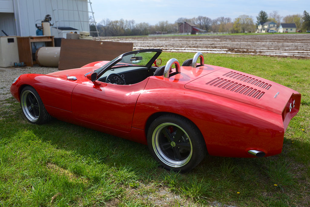
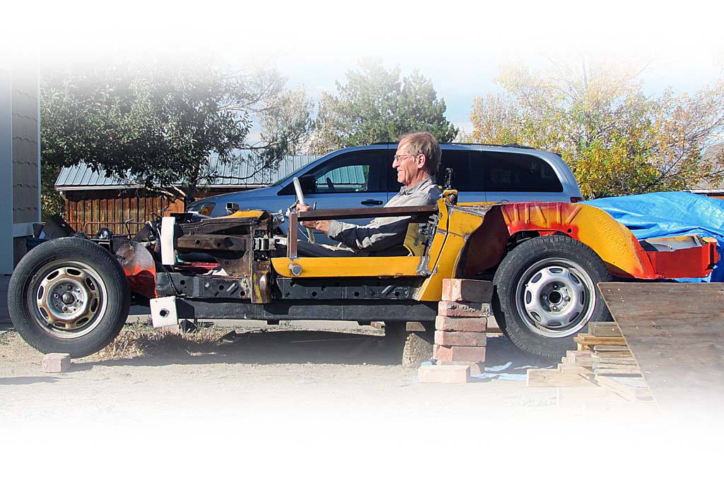
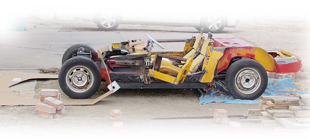
(R) AND AT LONG LAST -- THE WHEELS ARE ON THE GROUND. And, my, is it low!
Framing the Front


1st ROW
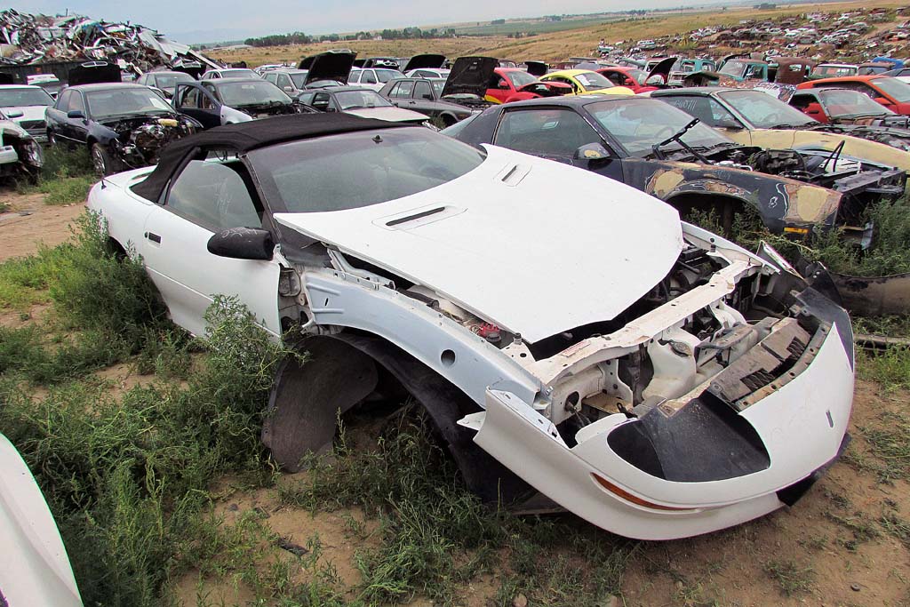
(L) The headlight-donating Camaro after I got the headlight assembly out.
(C) To better takes measurements, I printed out my drawings full-sized with a background of 3" squares.
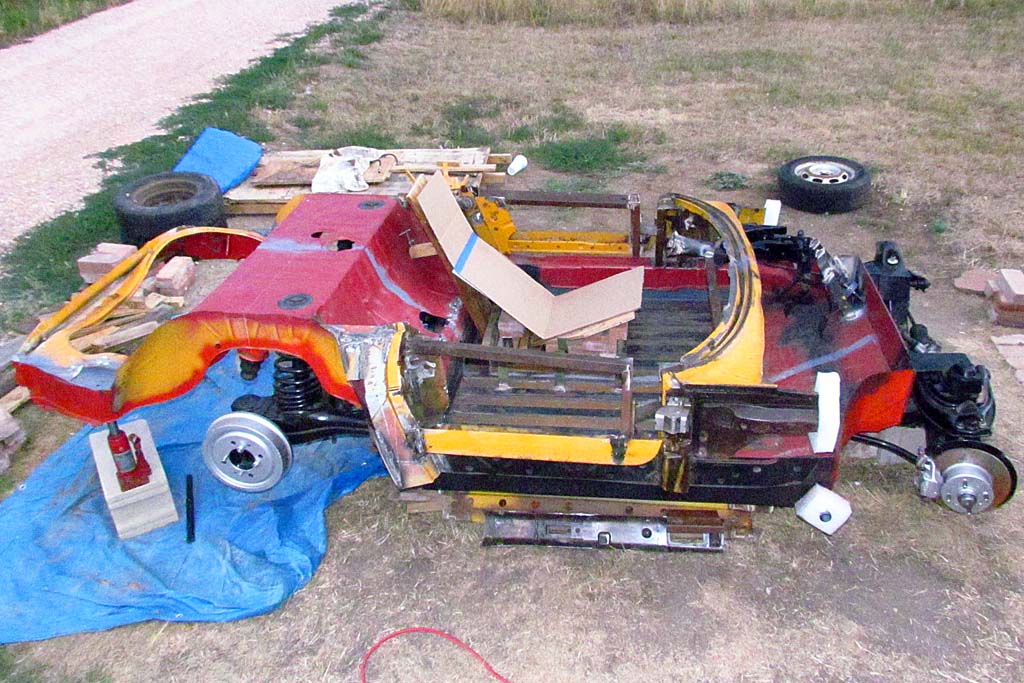
(R) The boxed-up negative cavity contour template
2nd ROW
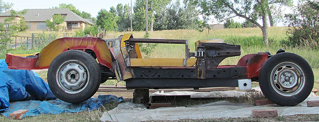
(L) The nose outline on the ground, which is suppose to be 3-1/2" above the wheelbase line
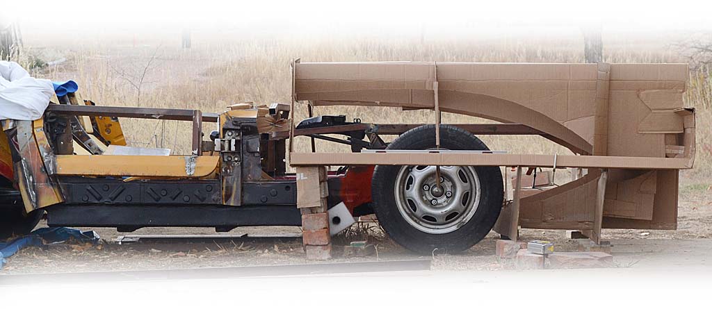
(R) Side view showing fender ridge and hood valley contours
(C) Looking into the cavity
3rd ROW
(L) The cross section at the headlight station
(C) The framing from the dash to the headlight station. The area betweem the dash and the front wheel well is for the gas tank.
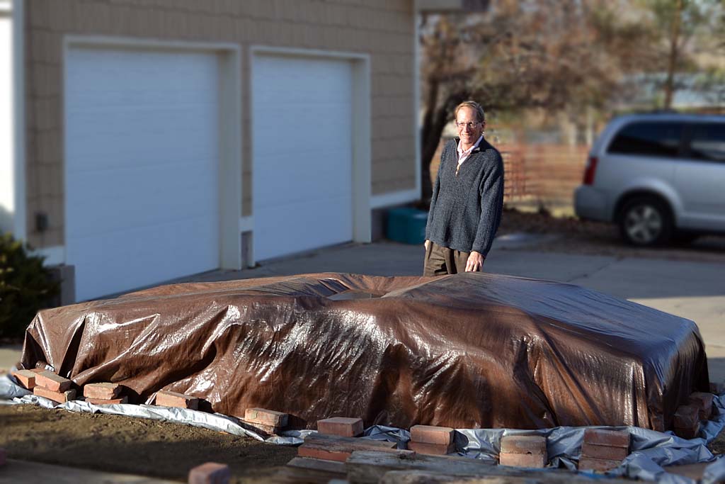
(R) The shape of things to come - the tarp hints at the outcome. It IS REALLY low!