
Contact: Rich Kurz Page content last updated February 17, 2024
The Construction Diary
2019
JANUARY
I got the files back from the designer.
They looked good and were done quickly and incorporated input for refinement.
But I have to learn to manipulate them to get my cross-sections.
I also tried to make 3D printed models of them, but need to learn how to prep the file to fill disjunctures.
I don't have time because I am departing for . . .
DETROIT AND BUFFALO - in WINTER!
The holidays passed and it was time to go to Detroit.
I scheduled appointments with the Buffalo Transportaion Museum, the GM Heritage Center, and The Henry Ford museum.
I Left Denver Sun. by train for Chicago to pick up a car Mon. to drive to Detroit where I stayed at an AirBnB.
On Tues. I crossed Canada to Buffalo for the time with the New York Worlds Fair Corvette.
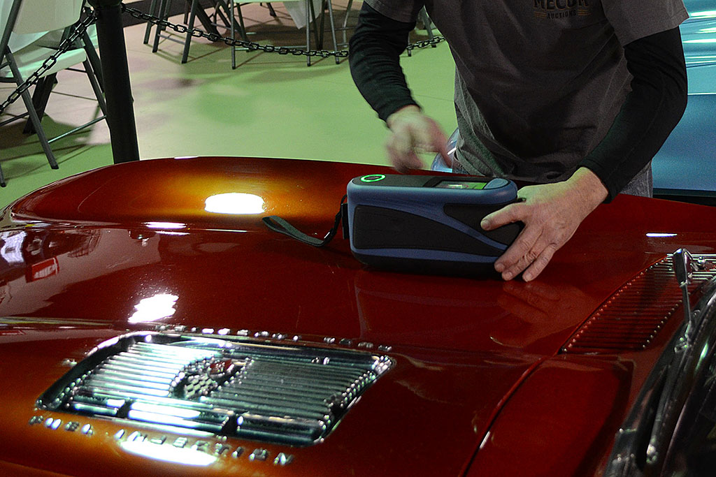
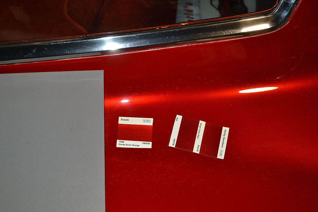
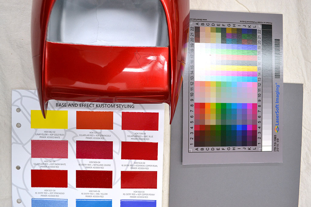
Fred Dorner from Urban Paint arrived with the spectrophotometer to make the readings while I pulled out paint chips and a gray card
and a color calibration card to photograph the car as many different ways and settings that I could think of.
The camera just cannot capture these trick paints the way the eye sees them.
After making the reading, I followed Fred back to the shop where he printed out the readings, selected the best of them,
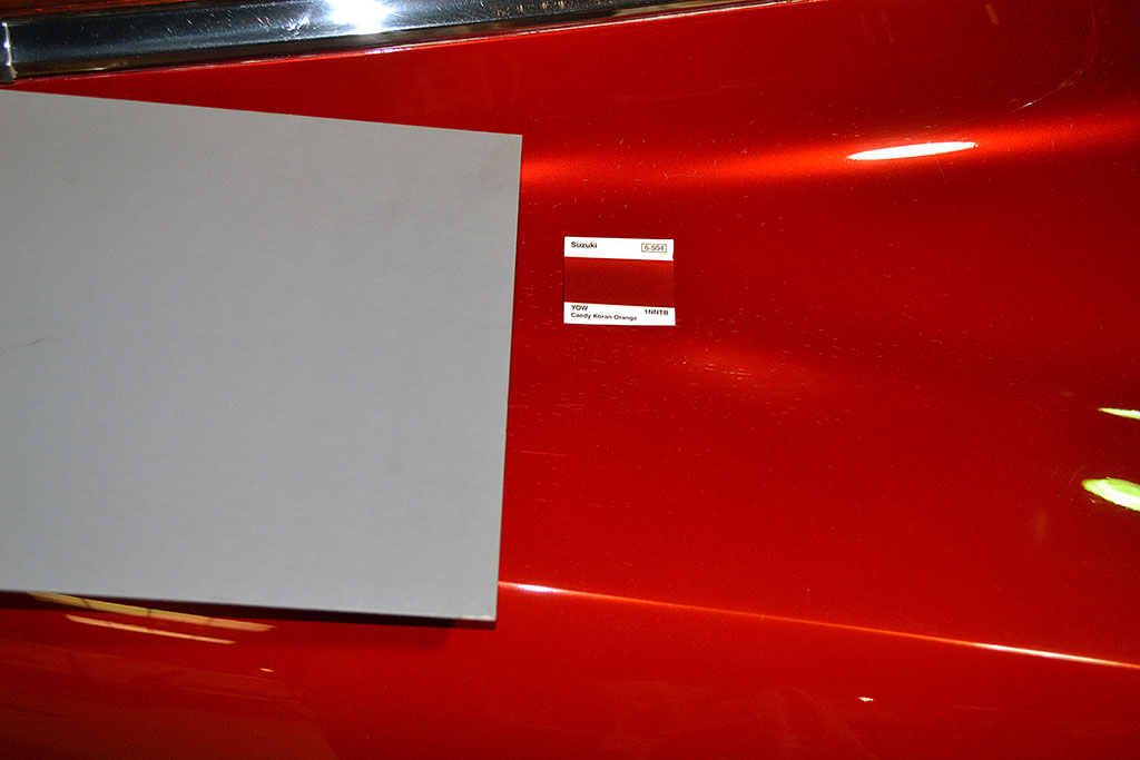
and provided me with numerous actual paint chips to go back and compare to the car.
I made it back before a gala took place at the musuem that evening and confirmed the closest matching chip.
It turned out to be a Suzuki motorcycle color, Candy Orange Koran - not exact but very close.
I returned to Detroit that night just as sleeting rain set in.
Weds. at 8:45 I showed up at the GM Heritage Center and met the archivist.
I spent the day reading all the documentation they had on hand on the Monza SS and GT, which consisted mostly of what are called S.O.'s (Styling Orders? - I forgot to ask).
I learned some of the creation history and the show history and some of the modification history.
To my surprise, I learned that the wheels are not true knock-off spinner wheels.
Instead, the spinners and their base plates unscrew to reveal four lug nuts.
I pinned down that the headlights originally were flipovers like on the C2 Corvette.
Those were changed to the current static, glazed-over, nose lights immediately after the car's introduction at the New York Auto Show in April 1963.
I skimmed a lot of pages that day.
Thurs. at 8:45 found me there again. They arranged for me to join a scheduled tour that morning to spend time in the display area.
I got to hang out around the car and study and examine it under different light angles.
Since my visit in 2016, the overhead lighting had been upgraded to LEDs.
Now the color hue of the Monza looked slightly redder instead of orangey.
I could also see subtle color differences on various parts of the car.
It was especially noticeable between the engine hood and the adjacent rear deck behind the seats.
By using highlight reflections, I could also discern the original flipover headlight outlines, even though they had been filled in and smoothed over.
That confirmed that it is the original body.
With the new photos, I hope to confirm the position of some landmark points on the body so that my digital model can be more accurate.
And I have a better understanding of the fender ridgeline and the pinching-in of the contours in the upper door area.
I think I was the last one out.
I spent the afternoon reviewing their image archives.
I was very intrigued by the pre-production version of the Monza SS, the XP-782.
The fiberglass full-sized model was well-developed by Nov. 1963, and the engineering department even created a running version in '64, although it was not as good-looking.
But for unspecified reasons, management cancelled plans to produce the XP-782 in Dec. 1963.
But at the end of two days, my time was up and I left the GMHC behind once again.
There is always more I could have done, but I achieved, I'd say, 90 percent of my goals there.
Friday morning found me at the grounds of "The Henry Ford" at the Benson Ford Research building, the home of their research library.
John Shetler from Painters Supply arrived with the spectrophotometer and, with the archivist, we proceeded to a conservator's room
to examine the 1/9th scale model of the GMX concept car from the Futurama II at the 1964 New York Worlds Fair.
The model still has beautiful paint, but then my first setback of the week happened.
The spectrophotometer had lost its calibration because of the cold.
I took what pictures I could with my paint chips and calibration cards, and went out to spend the rest of the day in the musuem.
But John did not give up and wanted to try again, and headed back to his store to recalibrate the meter.
The archivist agreed to let us return that afternoon, which we did and succeeded in getting the readings.
It turns out the model most closely matches Mazda Soul Red.
In my opinion, the model has slightly more cherry red color to it.
It is a gold base paint and not silver as I thought viewing a photo of it from the web.
So my week came to an end, with success at all three musuems.
And I even skirted the polar vortex as I headed out of town and off to Seattle to pick up a car to drive home (a '96 Olds Achieva SC coupe).
But that is a different story.
Once back home, I can have the paint readings made into paint, and enter my new photos into my digital model in Photomodeler.
And then begin to carve the body.
FEBRUARY-MARCH
Processing. . . and frustration
Processing my photos in Photomodeler is slow going.
The new data is creating a version of the body that is longer and also skewed from the earlier version.
It is puzzling because I am using the same landmarks and dimensions for calibrating.
It is indeed filling in the missing areas, but how to integrate them?
The color matches are not formulated yet.
I learned that the 64 NYWF Vette color does not match the actual Monza, but is darker when compared to the actual article.
And just looking at it, one could see that the GMX model was redder than the Monza.
Is the color on the Monza original?
Well, I remember from 2016 that the inside edges of the trunk seemed to have a flat finish - perhaps the base paint without the trick top coats.
IF the Monza still sports its original paint. . . then what I see today is the original color but after repeated touch-ups.
That explains the different shade of the engine cover, which was reworked in '65.
Arguing against it is the overspray on the frame both front and rear, but that could have happened in touch-up, so it is not conclusive.
Does anyone know someone who worked in the GM Styling paint shop in the 1960s?!
APRIL-MAY
MORE PROCESSING . . .
After six weeks (after hours)I stumble across a way to better orient my digital model.
It brings the 2016 data into near synonomous alignment with the 2019 plotted points.
Overall, it looks more accurate, but some dimensions don't quite match published ones or some of my measured ones.
But I can move on again.
AND THE PRODIGAL CHASSIS RETURNS HOME!!!
The engine is installed and it starts and runs at the shop.
On May 8, I roll it back into my garage, and there it is coaxing me to finish it up so it can run on its own!
With anticipation, I finally place the gas tank forms I made of the fender sides between the front well and the door
(see JUNE-JULY 2018.)
As best as I could align it, it looked good for adding an extra gallon or two to each side tank.
But it did show up a fit problem.
The rocker panel below the hood and door curves in a lot, which I did not realize when I welded in the new floorpan.
After some noodling and discussion with my neighbor, I decide I must cut it at the right-angle bend and bend in the now-cut-in-half L-angle piece that made the corner of the pan that runs front to back.
I make that cut, but it requires some hard cutting away of metal at the front corner where the cross-over pipe for the gas line is located.
That was a strong point. The pipe will have to be shortened so that the connection from the gas tank on each side to the cross-over pipe occurs inside the frame in the footwell area behind the wheel well.
That means that the gas tank portion that extends past the frame to the fender panel cannot go below the top of the frame member.
Otherwise it would require more plumbing to drain, and I want to keep this car simple - and trouble-free!
JUNE-NOVEMBER
Slow-Down: Finalizing THE Drawing
JUNE - The first order of business on the chassis was to finish the brake lines so I could have brakes and clutch.
Two small panels the front brake lines needed to pass thru were welded in place and the lines reattached.
I just needed to connect the master cylinder reservoir. It's a single reservoir for both the brakes and clutch.
But a problem became evident. The old 412 reservoir was too tall if it had to sit on top of the master cylinder mount welded to the top dash crossmember!!!
Now THAT could be a SERIOUS problem if . . . IF . . . I had plotted the correct location of the hood at that point! How to verify? How to solve for it??
SOLUTION #1 - Find a low and wide reservoir. But again, HOW low? And the existing ones tend to be round and tall or rectangular and tall.
I did eventually find one for a early-70s VW bus, I think it was, that was lower, but made only for the brake master cylinders.
Because of the slope from the hood up to the windshield, complicated by the recessed air intakes, space is very tight behind the dash on this car.
I will likely use the reservoir, but a better answer is to find that I have more room above the master cylinders than I thought.
Which led me to SOLUTION #2.
SOLUTION #2 - Finalize my drawings and make a final set I will commit to and build to!!!
When things don't all agree, like expected dimensions, a final measurement must be decided and set in concrete, and that is what I faced.
The best measures off my drawings had the car one inch longer and one inch wider and the wheelbase one inch shorter than the published dimensions.
I went into my program, plotted more points all around the car, tweaked some curves until they were smooth, deleted problematic curves and points, and refined specific points at known measurement locations.
Interestingly, as I kept adding points and tweaking points and curves, the dimensional discrepancies diminished.
But not completely, in spite of four months of effort, eradication, and refinement, I was hitting a point of diminishing returns.
I was improving things by only hundreths of an inch. What's more, the length was 1/4 inch too short, the wheelbase 1-1/2 inches too short, and the width still 3/8 inch too wide.
The reductions were approximately linear. I could not get things to work together to the published standard.
"But are the published dimensions correct?" you, appropriately, ask? My answer, in short, is, "Yes."
I can say that because I was able to confirm it with my own measurements of the real car, and with . . . a dramatic find . . . a photo of the orignal control drawing plan!!!
DECISION POINT #1 - I will disproportionally scale the width and lenght to match the published dimensions.
It turns out that one of the photos I discovered during my January trip showed the original clay of the car as completed.
And it just so happened that on the wall was the master drawing that the technical stylist makes and keeps current as the clay is sculpted and finalized.
That drawing becomes the reference for any other production drawings used to create the car.
But it was not self-evident it was there. It just looked like a blank drawing with a few lines on it.
But out of curiousity, I enhanced it in Photoshop and discovered what it showed.
I was able to determine the 5-inch grid lines typically laid out on those drawings, then used Hugin to do a perspective correction.
Unhappily, it only showed a three-view of the front of the car up to, but not including, the windshield. But enought to verify.
So I then traced it and compared it to my drawings.
There were discrepancies that I cannot explain. The biggest is the side view shape of the nose and especially its position.
The master is slightly higher in front and slopes more quickly as it goes back to the windshield, so that it ends a little lower than my drawing.
Although the Photomodeler-derived drawing is subject to more discrepancies in my opinion, the points were freezing into position, and they are made from the actual body.
Therefore, I will go with the Photomodeler-derived points.
Oh - by the way, I am not free to show the image since I do not have copyright permission. Sorry about that. I would love to share it.
DECISION POINT #2 - I will disproportionally scale the width and lenght to match the published dimensions.
In 2016, I was able to measure the wheelbase from rim edge to rim edge and it came out as 88 inches, as published.
In 2019, I attempted to measure the width, which was a challenge with my makeshift set up and no permission to touch the car.
Carefully aligning my lines of sight for the centerline and the point of maximum width (at the front wheel well edges, BTW), I got a doubled measurement of 64-3/16 inches.
That is only 1/4 inch more than the published dimension, and within the realm of error given my eyeball technique.
And the width could be made to match the discovered master drawing.
So I concluded I could trust the published dimensions, and the most accurate approach was to scale each view to fit.
Since my Photomodeler drawing focused on only the driver's side in detail, I would scale each view of that side and mirror image it for my final drawing.
DECISION POINT #3 - I will move the wheels to match the published dimension, and make a separate drawing with the wheelbase (WB) matching my chassis.
I can NOT explain why it is so far off! And nothing I did in Photomodeler could revesre the downward measurement it gave.
The front wheel seemed positioned correctly. It was slightly more than the published 39 inch front overhang.
So I explored if somehow the rear wheel was might have shifted, perhaps with an engine change.
Comparing the rear wheel position at WB=88" and WB=87-1/4" (which is the chassis WB) to a side-view photo I took in Jan., the photo matched closely the 87-1/4" WB.
Granted, it is difficult to take as accurate any photographic side views unless they are made at a distance. I could only get about 8 feet away.
But I centered on the wheel center, so that helped.
So the wheel wells, front and rear, do seem accurate to the car.
But surprisingly, there is a BIG difference in location between in locationthe front well on the master and the well on the car.
The front edge of the front well is 4-5/8" further back on the master than the car, and the front WB is 3-7/8" further back on the master from the car.
Again, I cannot explain it.
DECEMBER
Wrapping Up
The holiday season preoccupies the priorities. Little work got done on the project.
Thinking ahead, I need to move the chassis out of the garage so a working car can occupy the space.
I wanted to complete the floor pan cut on the driver side and get both cuts welded up.
That happened between Christmas and New Years.
Making the cut on the driver side went pretty problem-free.
But when I hit the front wheel well area, boy, did it smoke and smell!!!
I had hit old underbody weatherproofing. I should have wirebrushed it off.
It took about a week to air out so the rest of the family could breathe in the garage.
That was an unhappy mistake.
I had to cut carefully around the front wheel well and open it up to trim the crossover pipe back.
I learned from the experienced guys at NAPA that the fuel hose that will attach to it will not make a very tight bend.
So later I will have to weld a corner onto the pipe stub to attach the hose to.
One step forward, two more to go.
And again, my neighbor did the welding up. He's good and quick!
Now the rocker panels will fit without interference.
Check out 2020 for more progress!
Check out 2020 for more progress!
The Build--2019
January
1st ROW
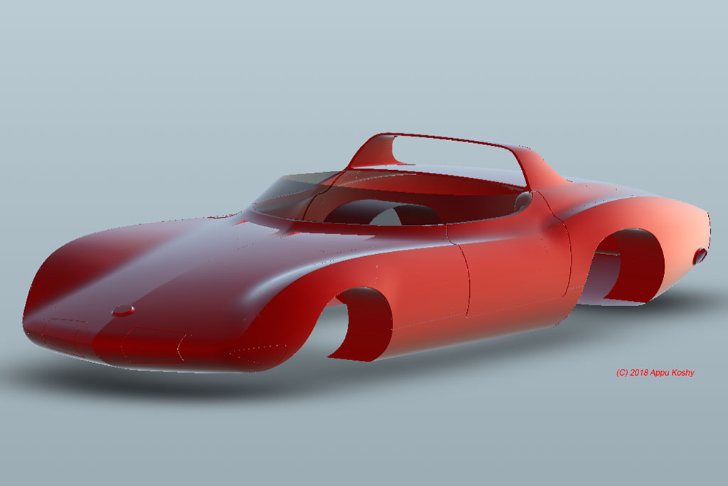
(L) 3/4 view of the 3D model
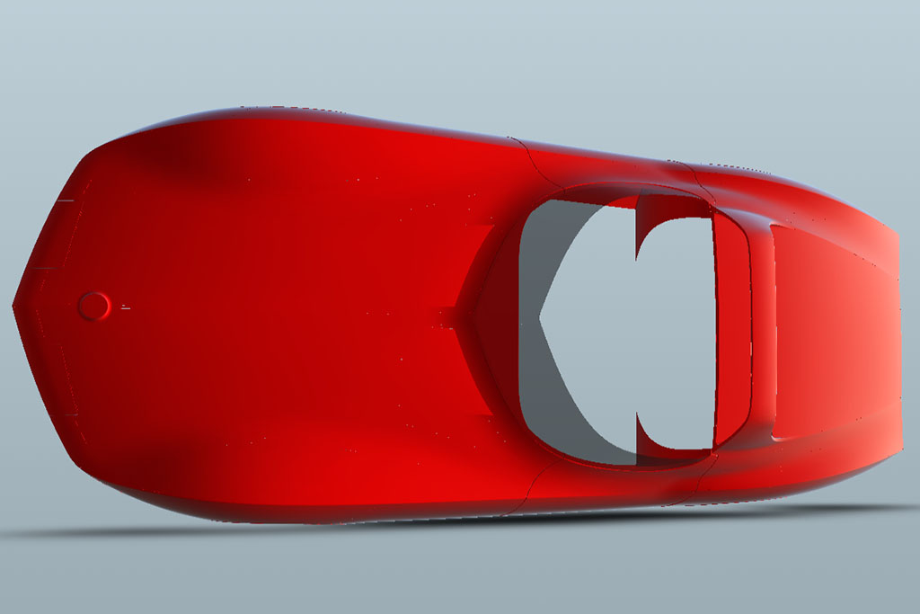
(C) Top view of the model
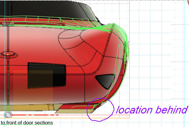
(R) A clipping of a comparison of my drawing to the model for refinement
BUFFALO TRANSPORTATION MUSEUM (Pierce-Arrow Museum)

1st ROW
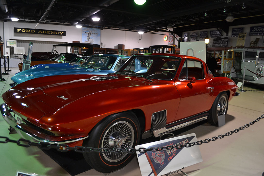
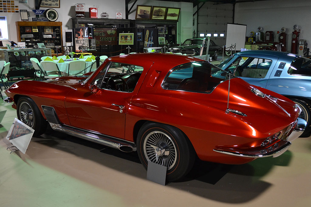
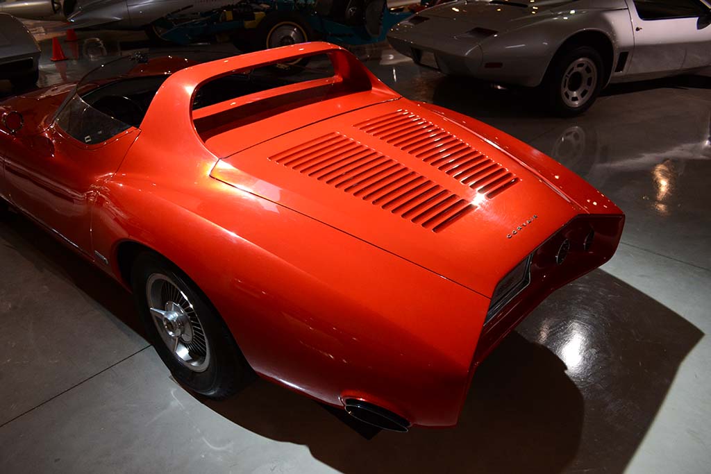
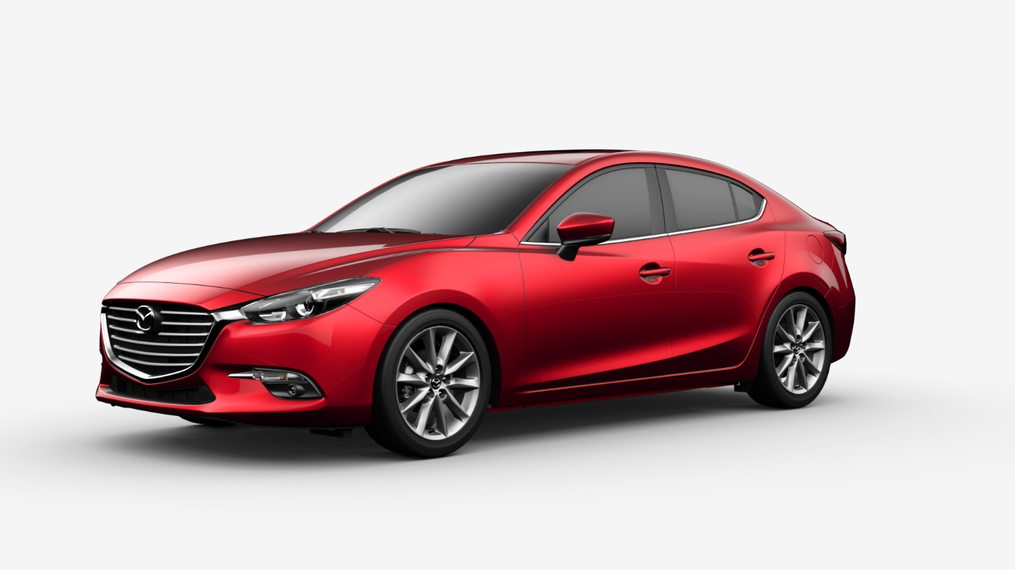
(L) The New York Worlds Fair Concept Corvette in its original paint, as I first saw it.
(C) In spite of multiple owners and actual street use, it's paint is still in good shape.
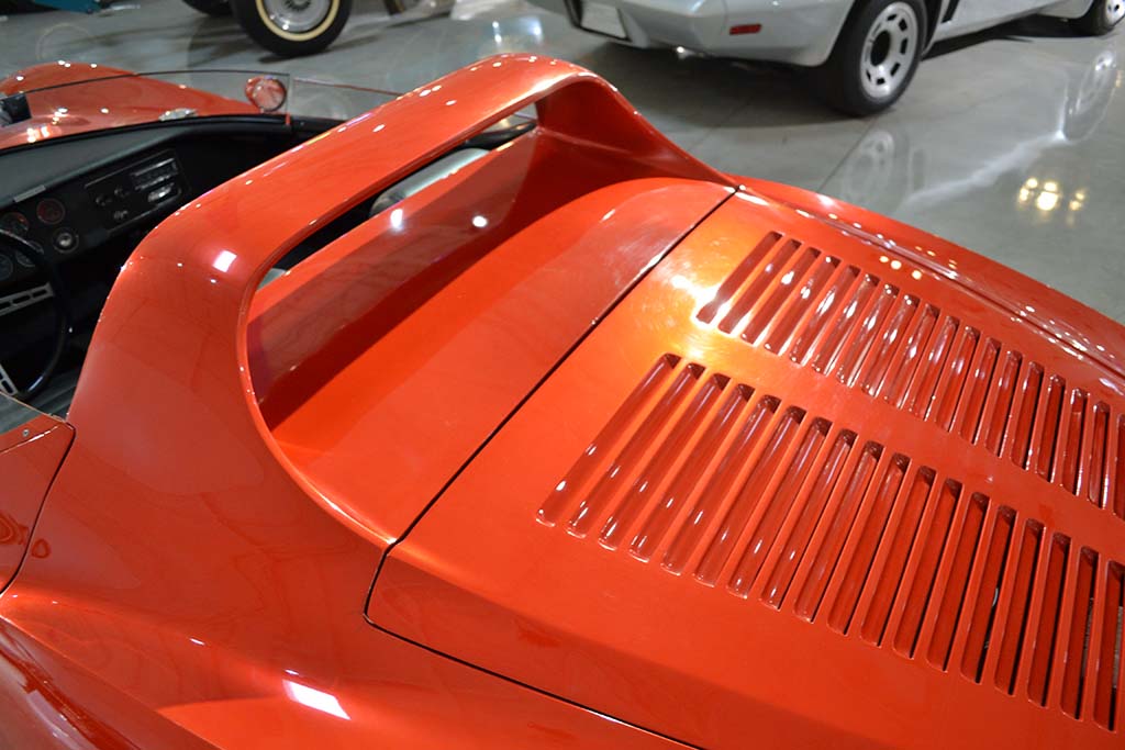
(R) Notice how dark-looking it is, both to the camera and the eye. It is reputed to have 14 coats of semitransparent paint over the base.
The edges of the hood and elsewhere are rounded with all the coats, and the paint has an unusual depth to it that only that many coats could give.
2nd ROW
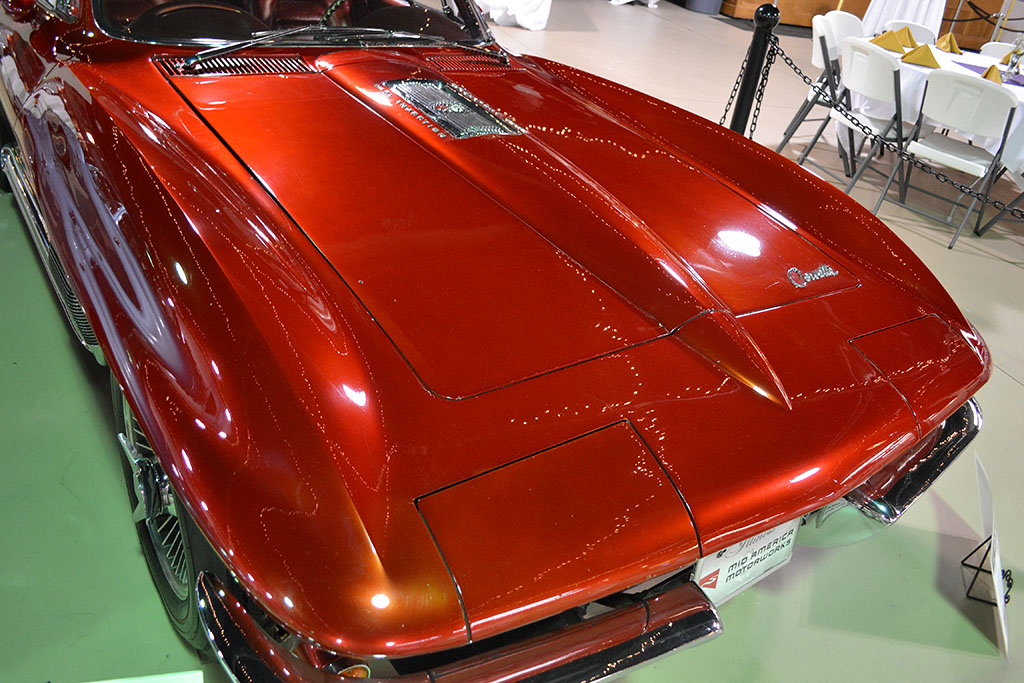
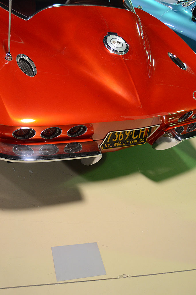
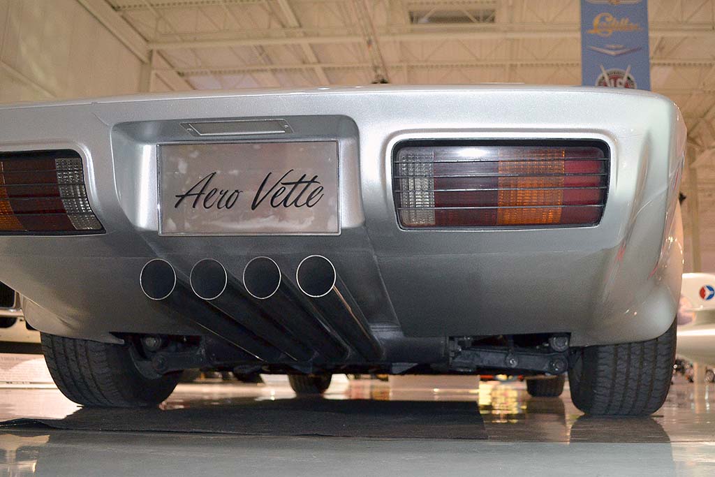
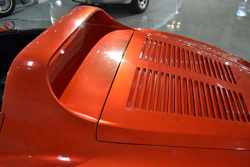
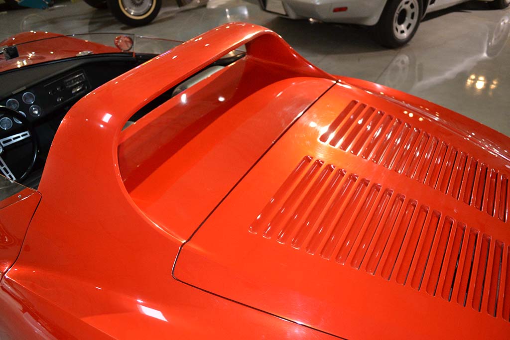
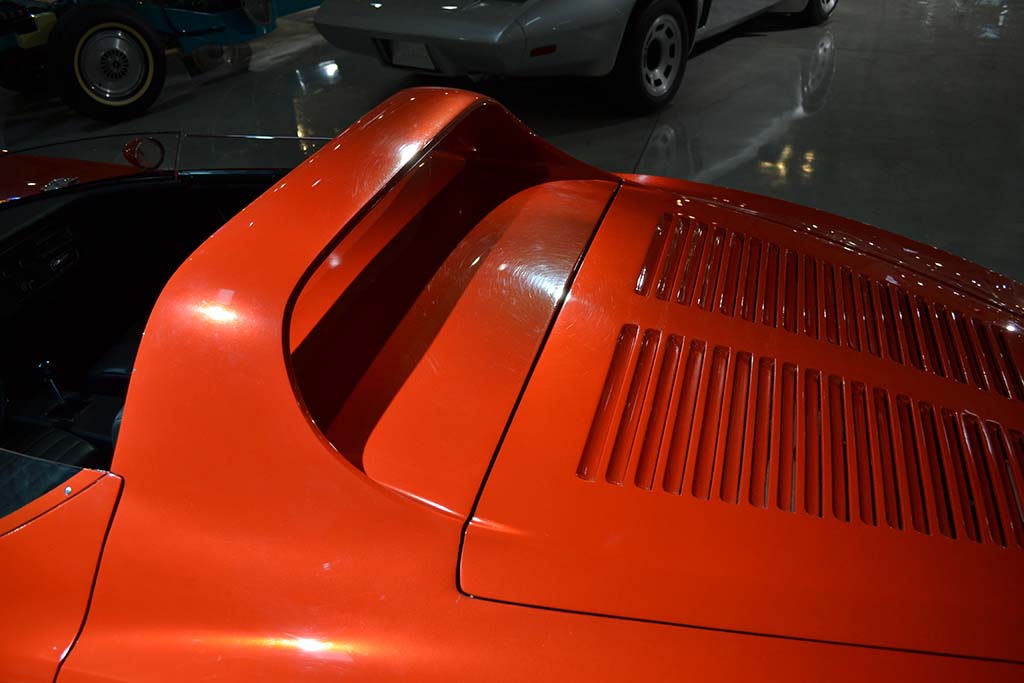
(L) The light was better on the rear and it looked more orangey in that light. The exhaust grills are nonfunctional, but recall those on the original Sting Ray racer.
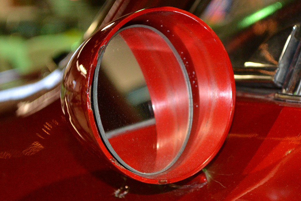
(C) It is possible that the paint on the inside of the mirror is the actual base coat without the semitransparent buildup.
(R) This shows the color reading being made. It was done in three locations and averaged.
3rd ROW
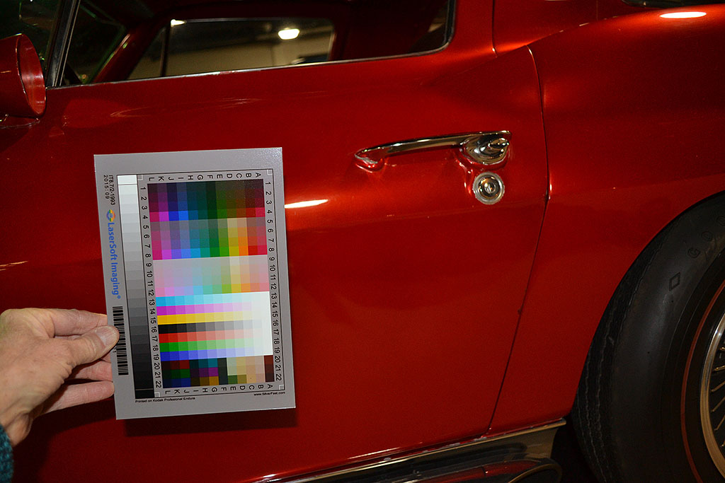
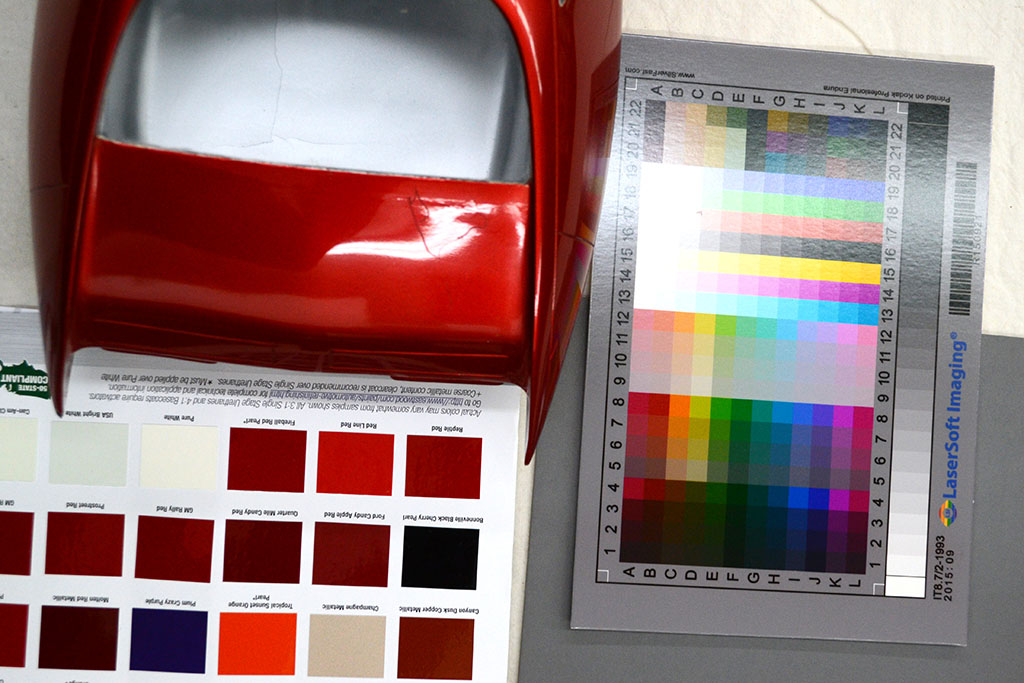
(L) Color card under strobe flash
(C) Gray card and the closest matching color according to the spectrophotometer reading and color database comparison. Close but still different.
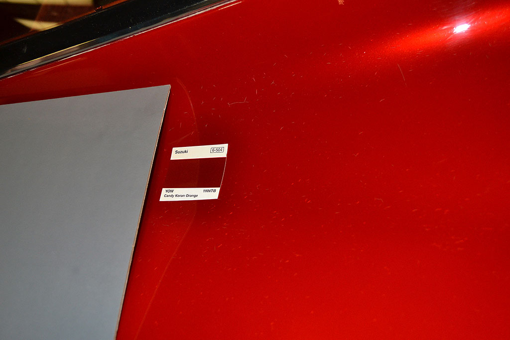
(R) Same view but from off-angle. Note how the chip looks darker now.
4th ROW
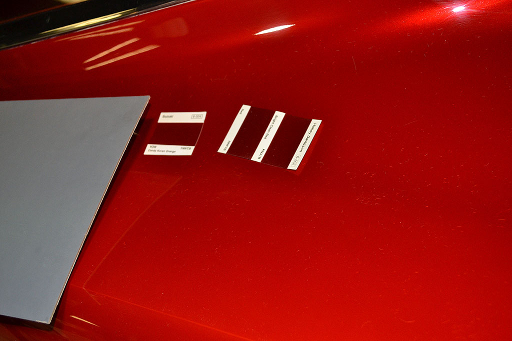
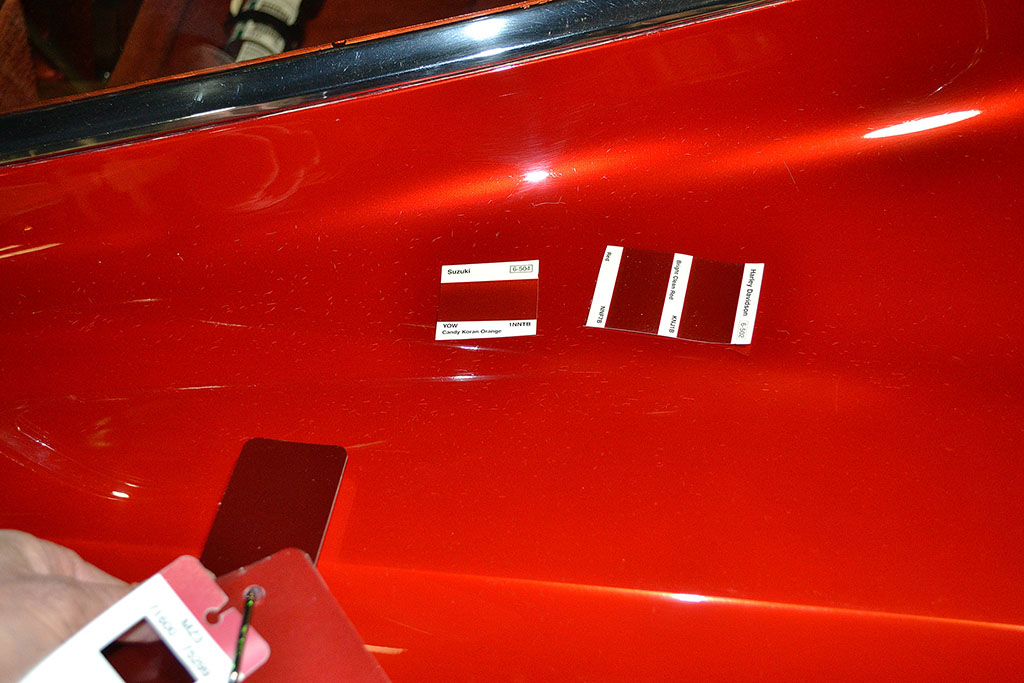
(L) The color chip plus the next two closest matching chips
(C) Seen from a different angle . . .
(R) And with another paint chip
GENERAL MOTORS HERITAGE MUSEUM
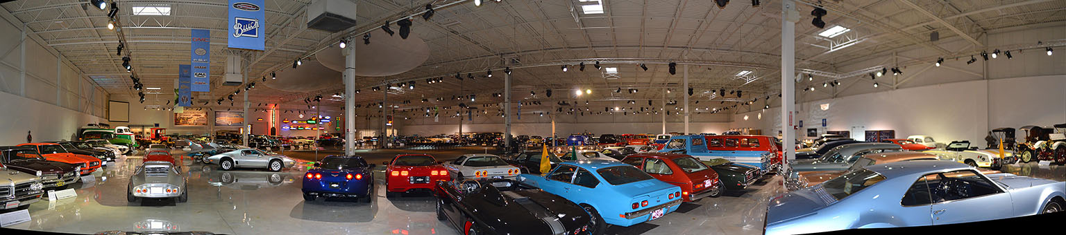
1st ROW
A panorama of the Heritage Center on Jan. 25.
2nd ROW
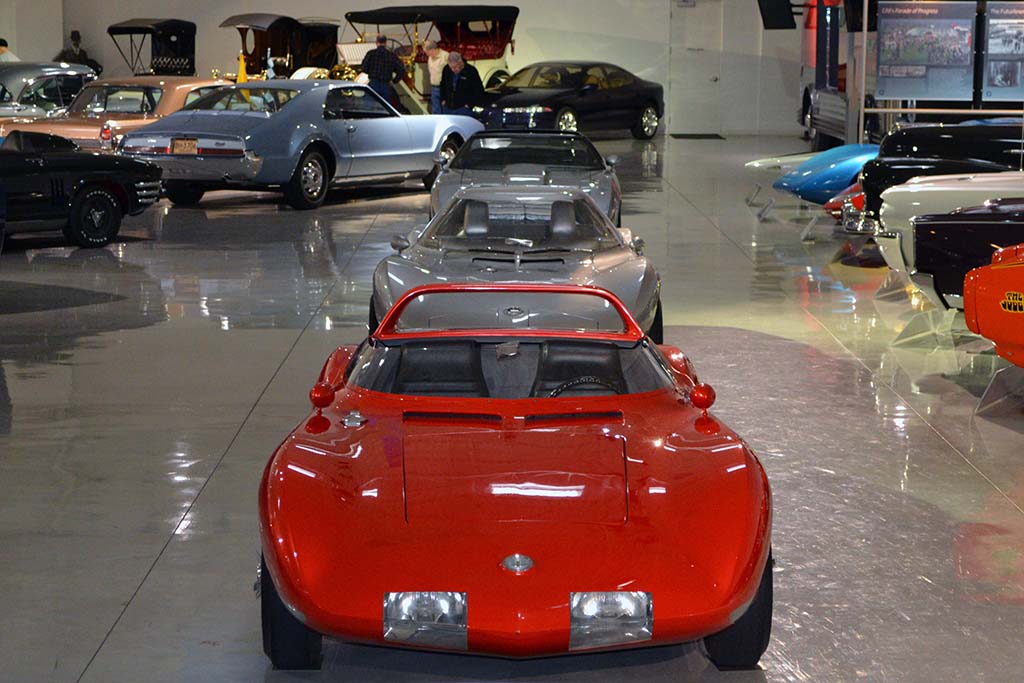
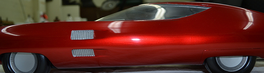
(L) The Monza SS and the Monza GT. The GT was not there on my first visit.
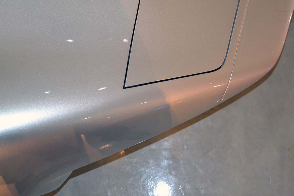
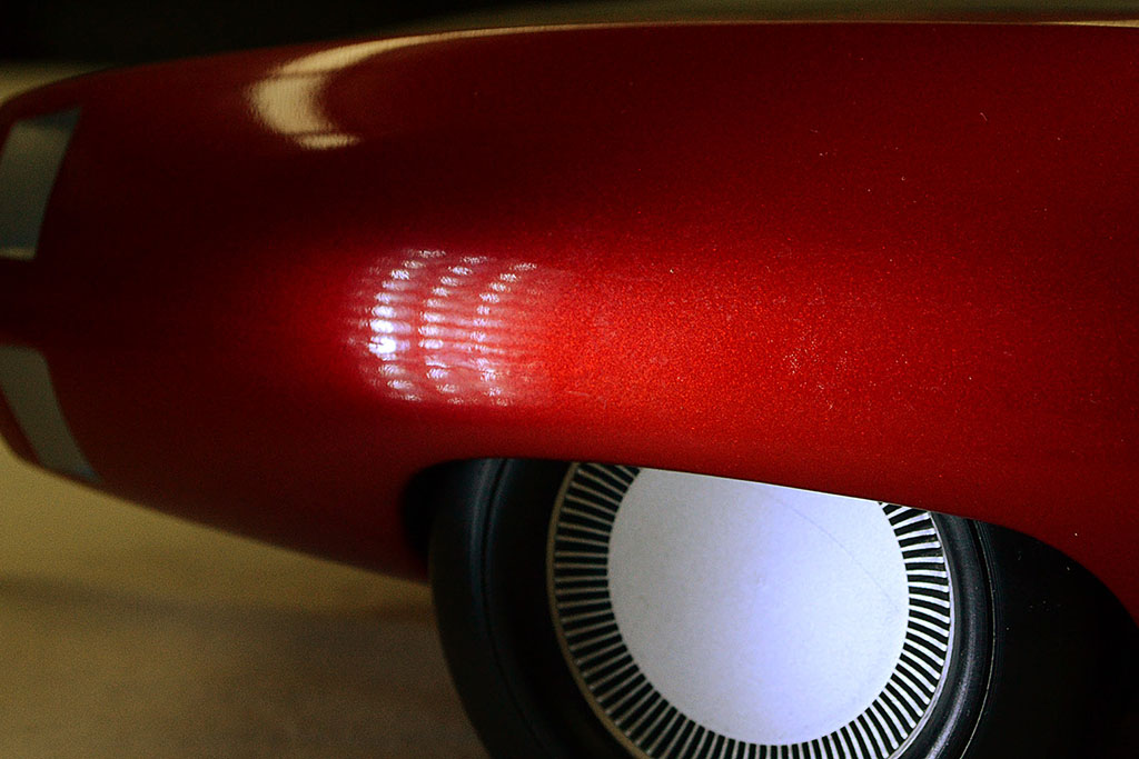
(C) A closeup of the paint on the Aerovette. It looks very much like that on my model.
(R) And a closeup of the paint on my Aerovette model.
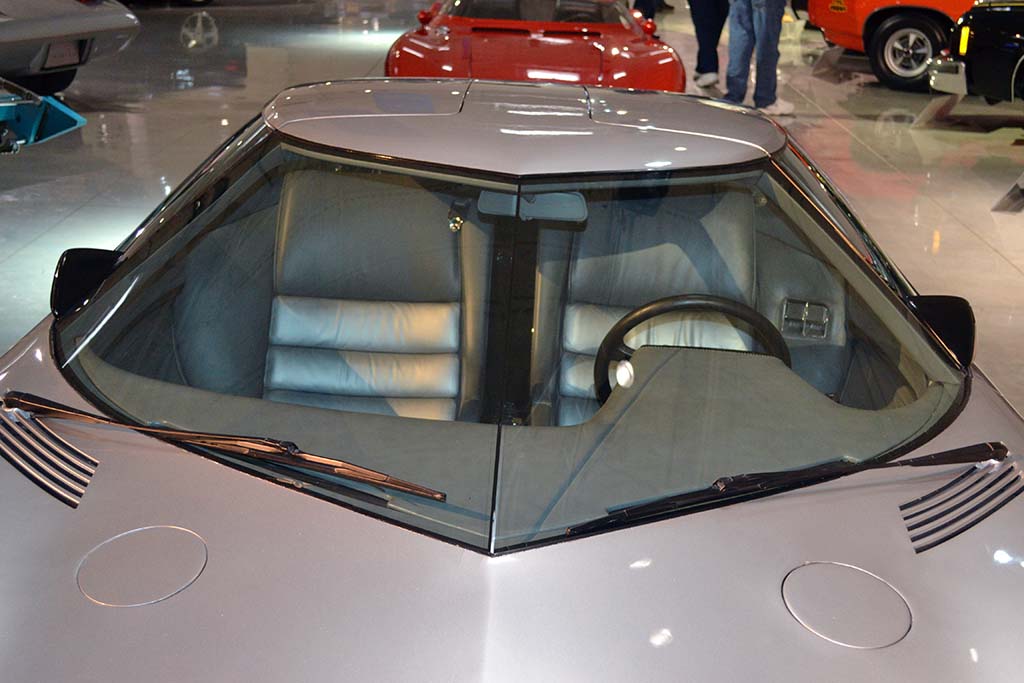
3rd ROW - Aerovette details
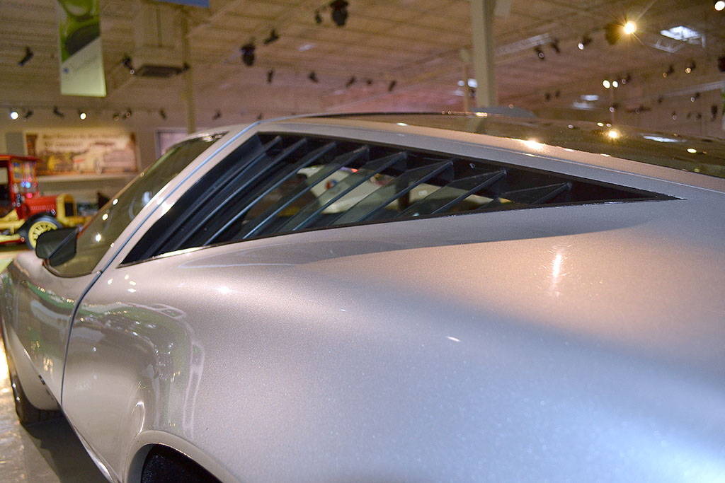
(L) The space between the rear quarter windows glass shutters is open to the engine compartment.
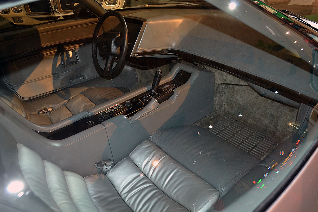
(C) A view of the interior. Note the two shades of gray.
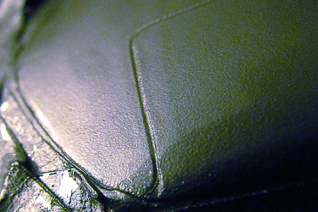
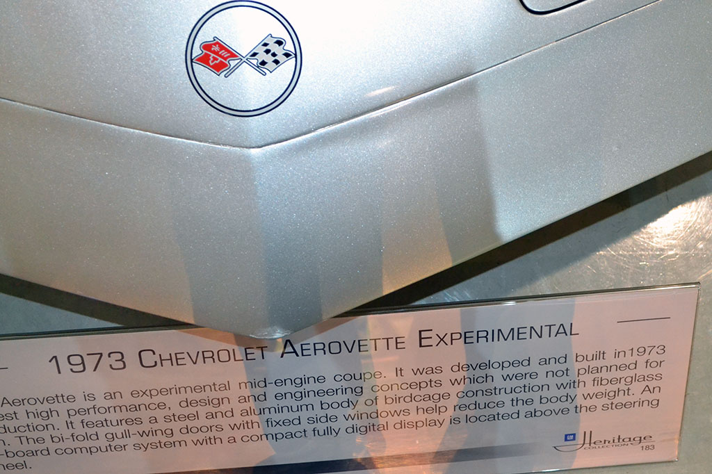
(R) A detail showing the sharp corner of the headlight cover.
4th ROW
(L) A look-down view of the nose. It is more rounded at the tip than I expected.
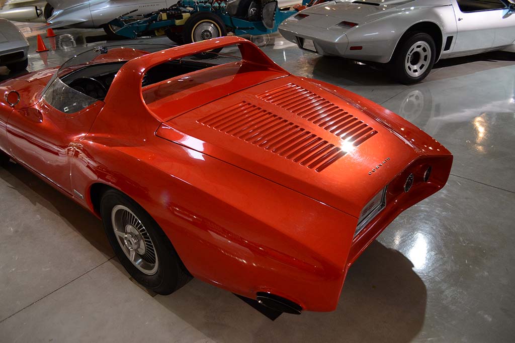
(C) A study of the rear with the camera on the floor.
(R) The windshield looks to be made from two pieces seamed together, rather than a single, creased-formed piece. In 2023, I asked a retired GM designer if that was so, and he told me it was a single-piece windshield.
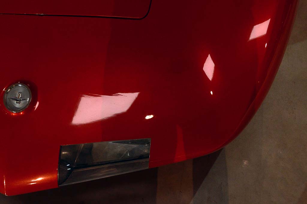
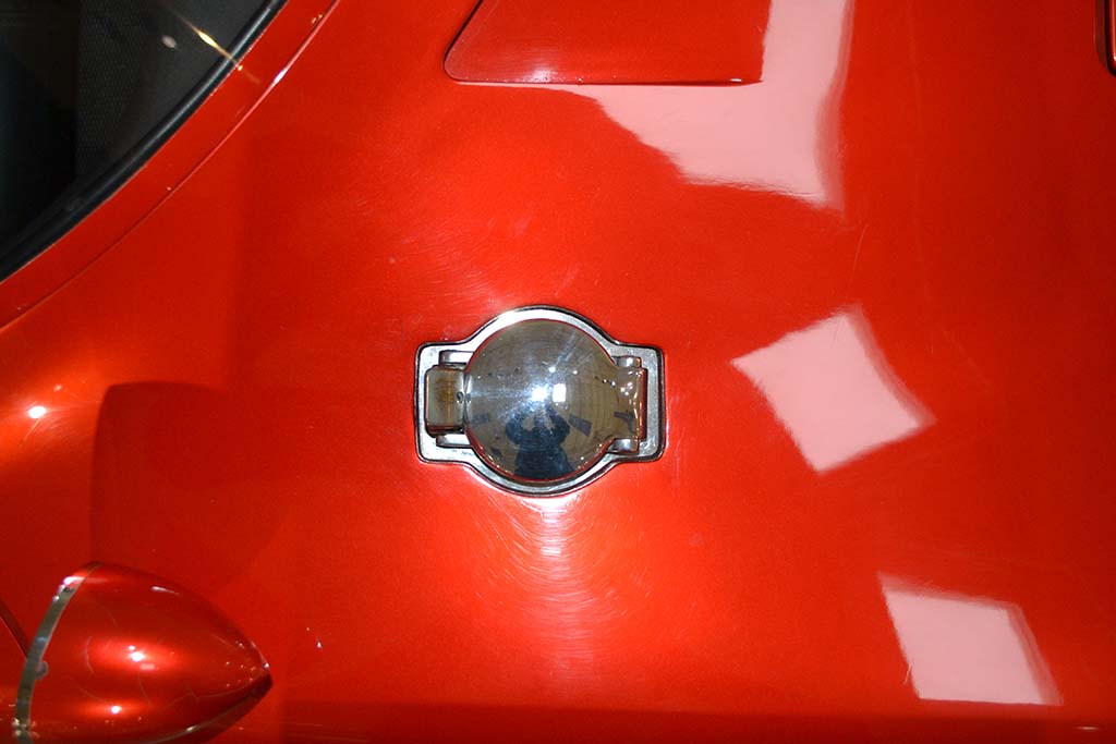
1st ROW
(L) Look carefully at the highlight above the headlight. You can see lines where the original flipover headlight was seamed over.
(C) From a different angle, the corner of the flipover headlight shows itself.
(R) A straight-down view of the gas cap. It measures 3-1/4" in diameter.
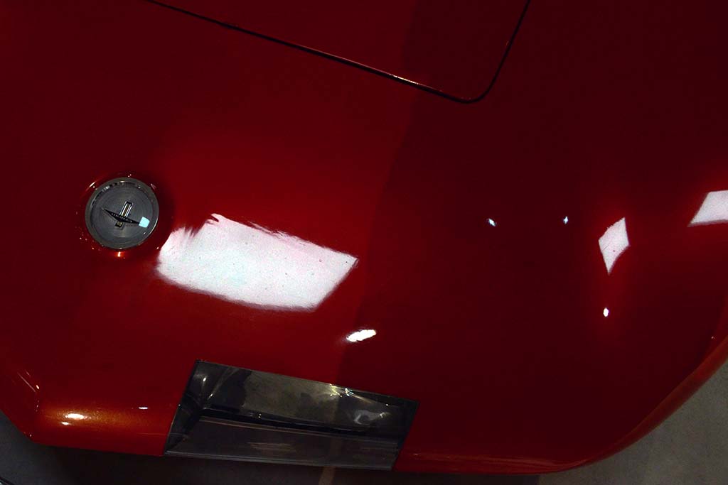
2nd ROW
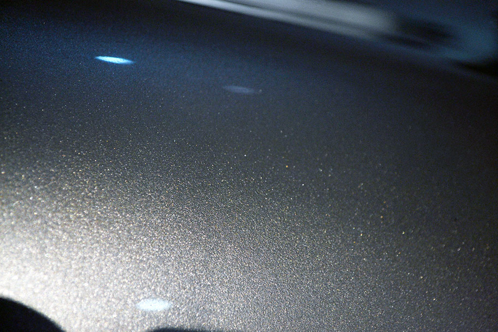
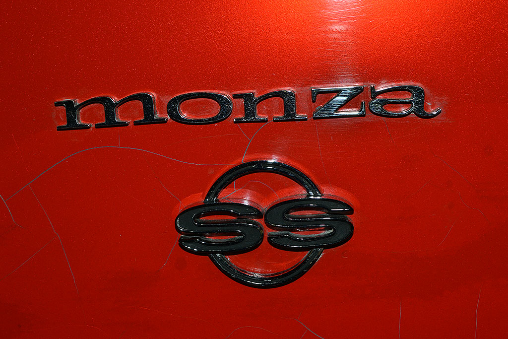
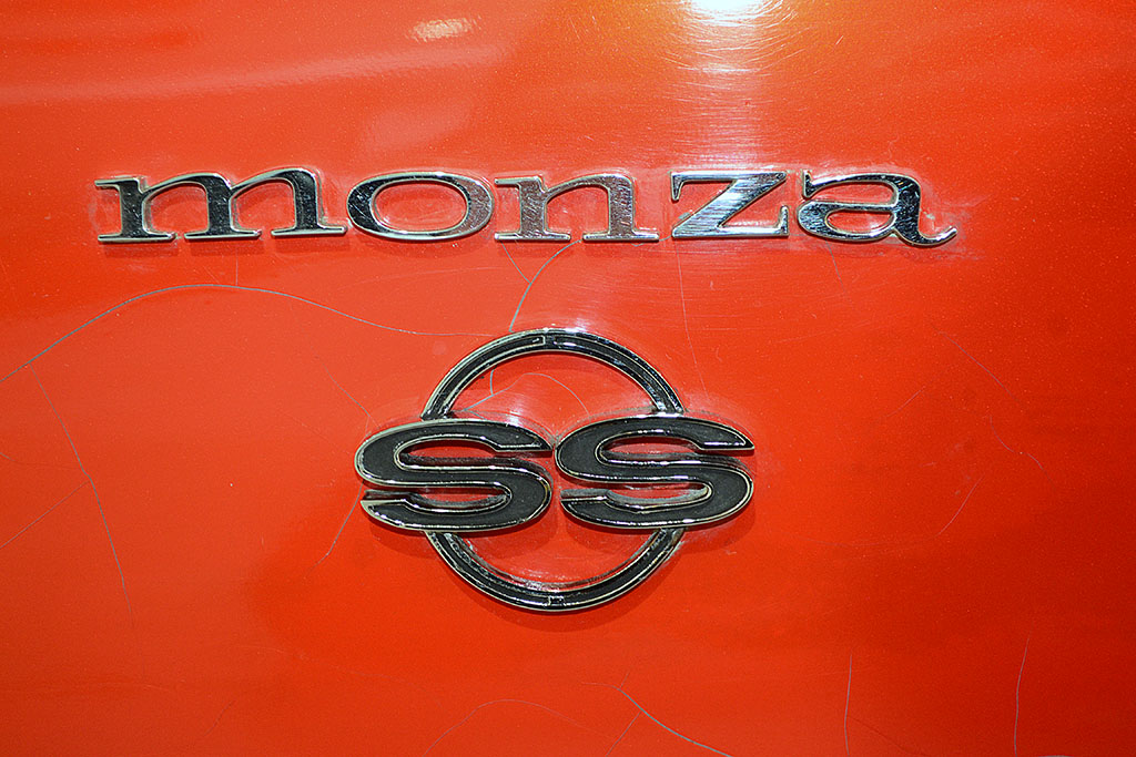
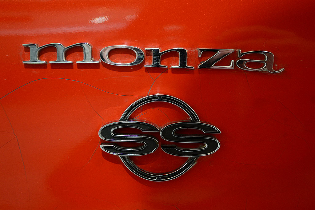
(L) The passenger-side emblem taken with a flash. Note the darker touch-up spots, and the reflecting speckles above the name.
(C) Same view also with a flash but set to automatic exposure. The color shows but not the speckles.
(R) And how the same view appears without a flash under the room lights. No speckles once again, but a deeper hue of orange-red (or is it red-orange?!?}
3rd & 4th ROWS - Color/Lighting Comparison Pairs
(L) (top) General room lighting - mainly LED, no flash; (bottom) and under direct spotlight
(C) (top) General room lighting - mainly LED, no flash; (bottom) and under direct spotlight
(R) (top) Illuminated by camera flash (Nikon D3100); (bottom) General room lighting - mainly LED, no flash
THE HENRY FORD (Museum)
1st ROW
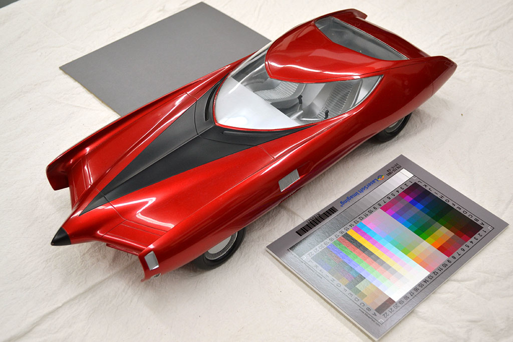
(L) The 1/9 model of the GM-X Stiletto sports coupe (XP-759) on the conservator's table
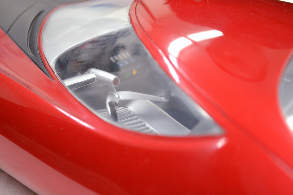
(C) A close-up of the interior. The car and model appeared in the Futurama II exhibit of the New York Worlds Fair, 1964-1965.
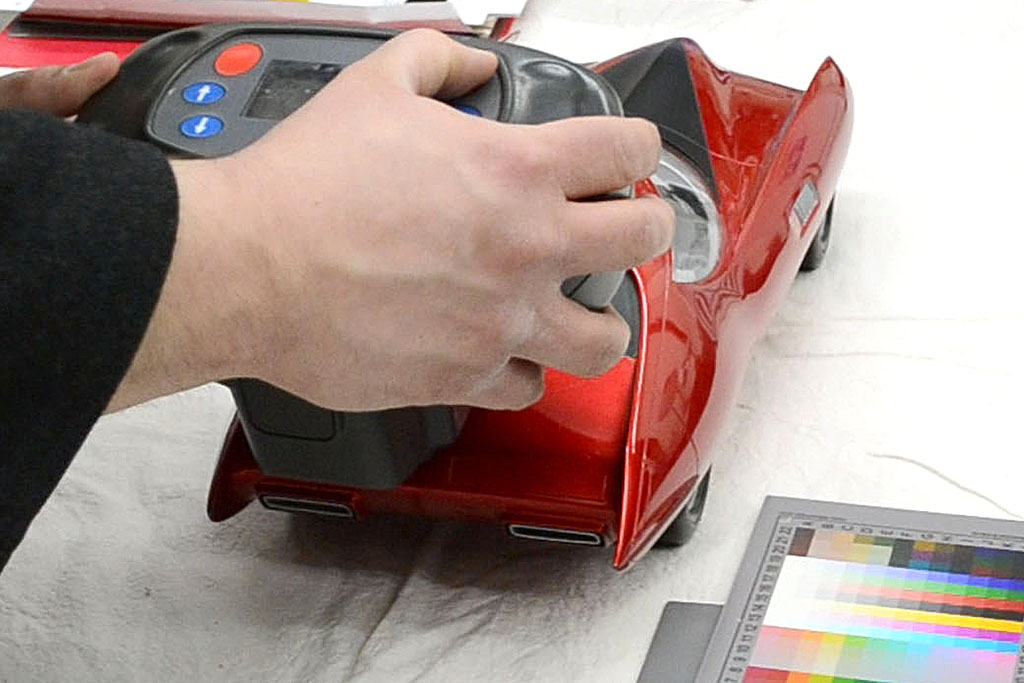
(R) The color reading being made. It was done on the roof and the rear hatch.
2nd ROW
(L) After the failed first attempt, I compared it to some HOK colors. . .
(C) And to some Eastwood colors.
(R) This photo shows the paint illuminated by a standard flashlight-type white LED.
3rd ROW
(L) This shows the color using the camera flash and color-correcting to neutral gray on the hubcap.
(C) The spectrophotometer found the closest match to be Mazda's Soul Red.
It did look close, perhaps more cherry red, with definitly a gold-looking base coat.
February-May
1st ROW
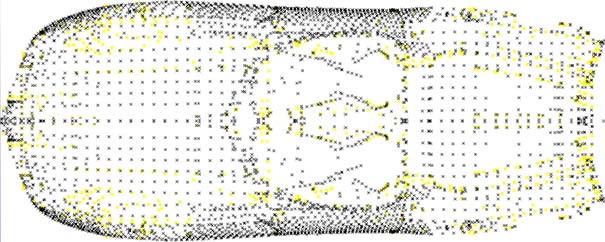
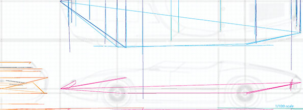
(L) Before my file went haywire, I was getting what looked like the actual profile for the first time.
Here are plotted points for the driver side that has also been mirrored to the passenger side. After aligning the two halves, it was scaled to the published length, which matched the published wheelbase that I also measured in 2016. The width scaled to 65.3 inches - greater than the published 63.8 inches and my measured 64.125 inches.
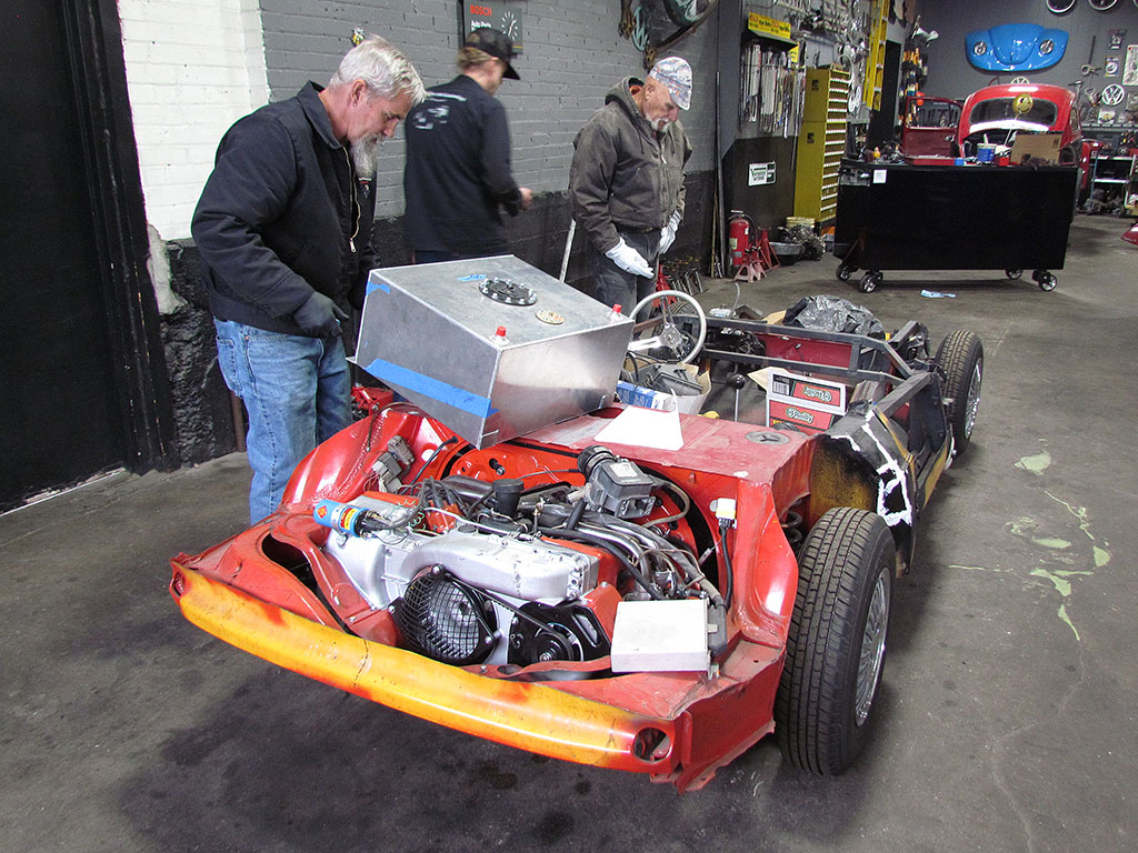
(C) The chassis in the shop at the run-up. It was a relief to actually hear the engine run. It WILL need a muffler.
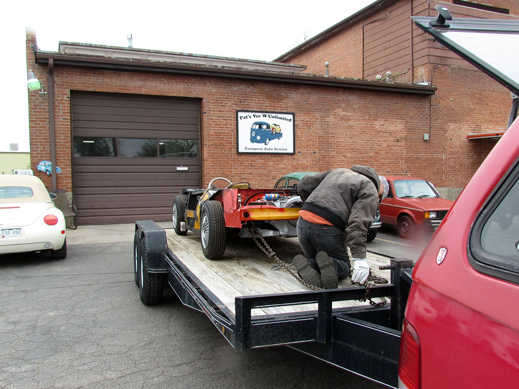
(R) The chassis on the trailer for the return home. Thank you, Pat, for all you did to make it work!
2nd ROW
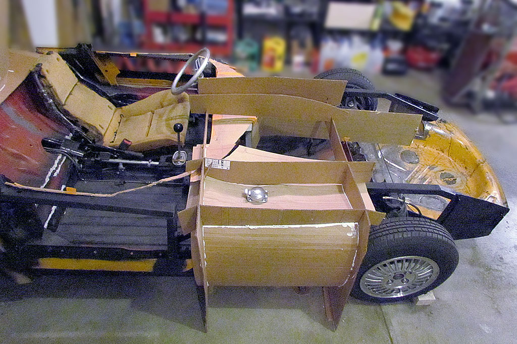
(L) Form viewed from passenger side and above. Gas filler position matches real car.
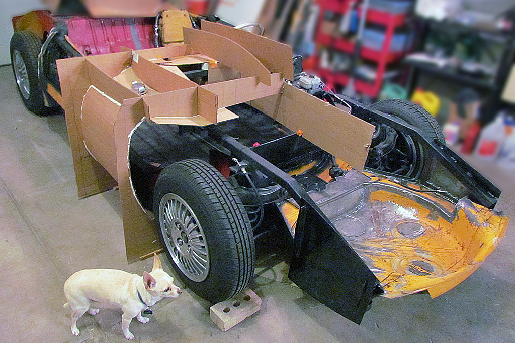
(C) Form viewed from 3/4 front, passenger side (chihuahua is for scale)
(R) Form viewed from front & above (same chihuahua, same scale)
3rd ROW
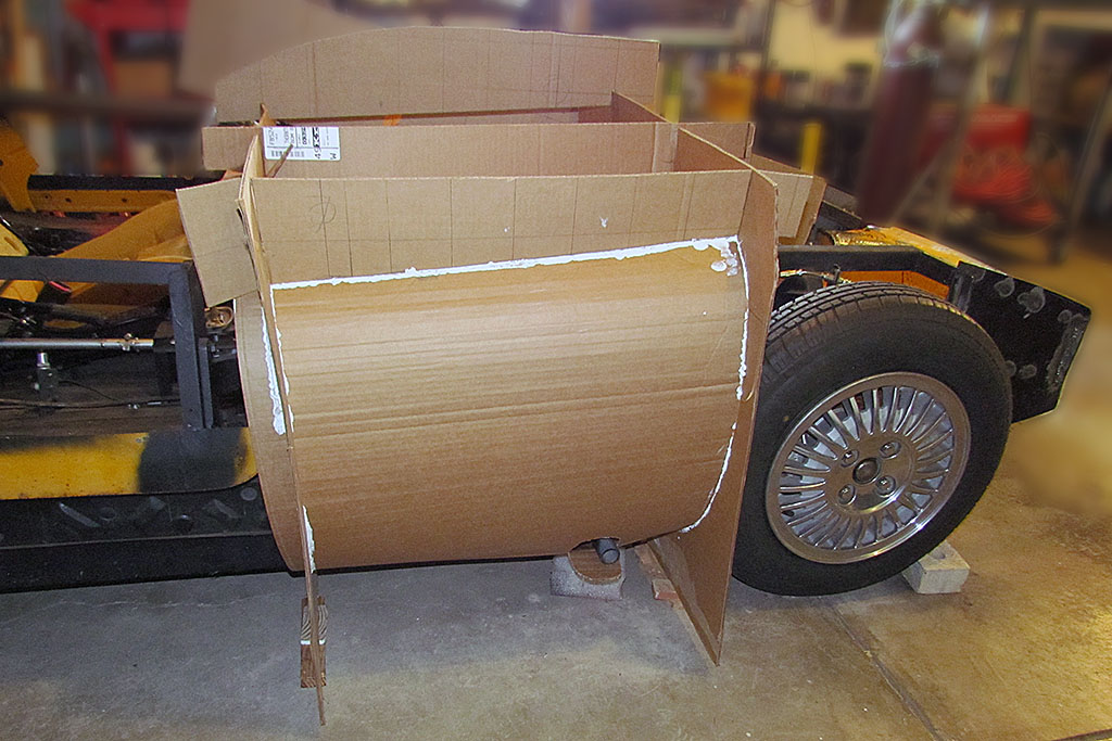
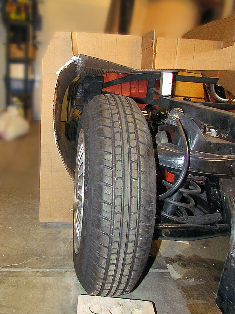
(L) Driver's side gas tank fender form (door on left, front wheel on right)
(CL) Form viewed from front, passenger side (right front wheel showing)
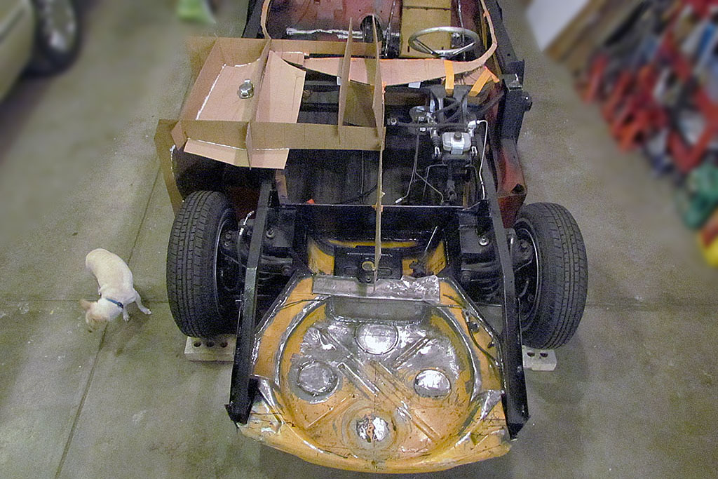
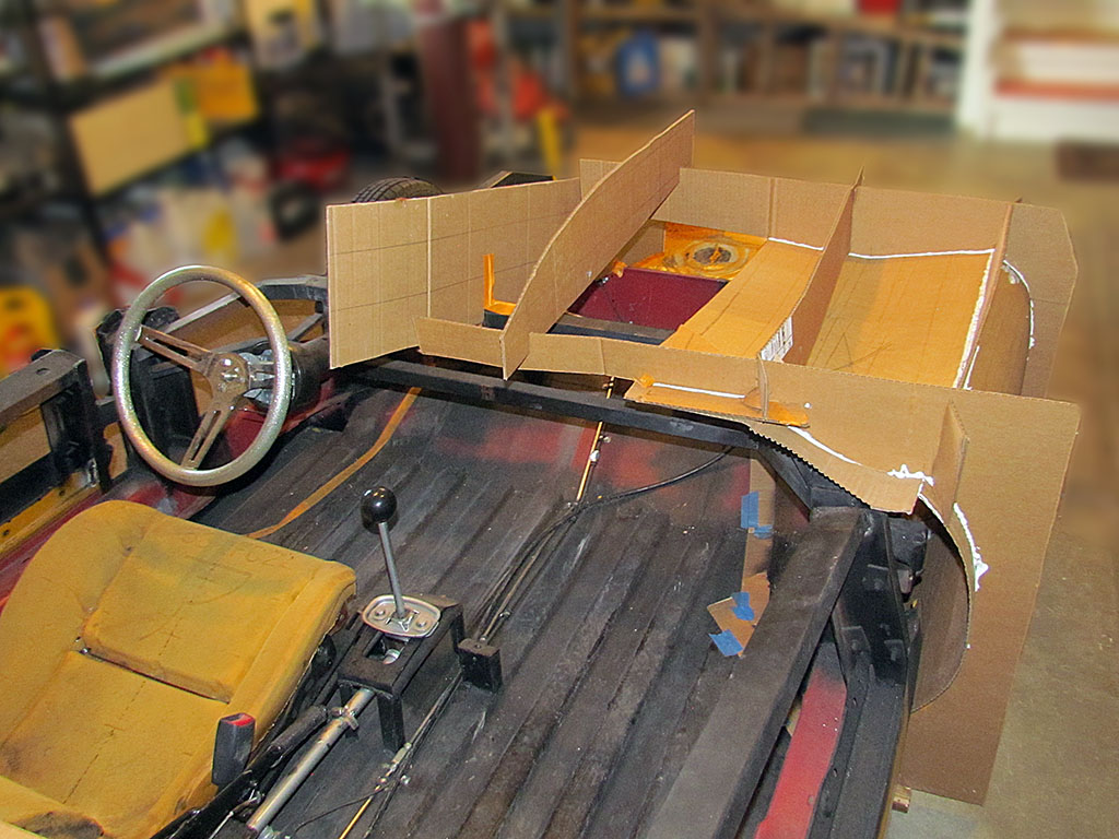
(CR) View from passenger compartment looking forward
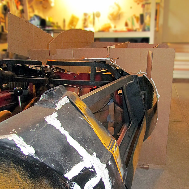
(R) Form viewed from rear, passenger side looking forward
June-November

1st ROW
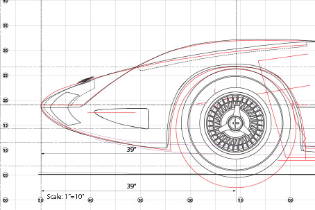
(L) 3-view plan showing the guide lines used to measure dimensions to various datum points
(C-left) Side view of nose comparing the Master drawing (red) to the Photomodeler contours (black)
(C-right) Side view showing photo of rear wheel and the drawing position at 87-1/2".
The photo also shows how much distorion there is due to depth between a perspective view and an ortho view.
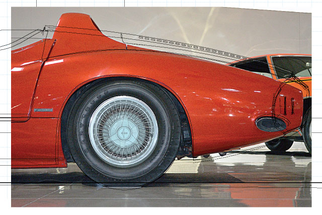
(R) Here is the wheel with a Blue Streak tire. Best I can tell, there are two sets of two that mirror each other.