Contact: Rich Kurz Page content last updated May 29, 2024
The Construction Diary
2018
JANUARY
It's a new year and a new life!
I drilled new spark plug holes in the engine tin, trimmed off an inch so make the driver-side tin
to fit the engine compartment opening after shifting the engine over when centering it,
fitted the fan housing, put the tinware on, bolted on the alternator, adjusted the cooling flaps,
and discovered where the thermo timing switch went.
While preparing photos for this page, I discovered I mislabeled cylinder 3 & 4,
which meant I might not have the engine at TDC!
Big problem for the distributor!! But how could that be?
the distributor key was at 12 degrees and the #1 rocker arms were both closed when I rocked the crankshaft.
Lots of reading later, and I learned a new term: "TWADDLE."
That is when the rocking motion of the arms overlap with one closing and one opening.
There is a brief moment when they are stationary and equal.
And THAT is what I was seeing on #3!
So I buttoned all the tin up and was back to where I started.
The coil posed a fit problem. Maybe the newer ones are slightly larger in diameter, but the bolt-down strap wouldn't bolt down.
First the retainer bolt hole was stripped, so I tapped a new one, going from an M6 to and M8.
Then I ground down the cast fins on the fan housing where the coil rested so the strap would bolt down. It worked.
Then on to the intake air distributor. I think it bolts to the engine housing using two case bolts.
But I want to be sure before undoing those bolts.
Then I scraped out gunk from the EGR valve and wondered if some of that was old seals.
I learned that the EGR is a hard to find part. And needed to pass emissions on a 1977 engine. More research.
So many little parts that I am missing.
MORE SPECS
Battery:
Group 42-1, 6-7/8"x6-7/8"x9-1/2"
FEBRUARY
Things are now dragging out on the engine.
Since I am going to have a good mechanic finish it up for me and check my work, I decide it is time to take it to him.
He tells me there is only one engine ahead of mine. I also learn that I do not need the EGR valve.
So there I leave it. I still need to adjust the brakes and fix the safety brake, make the front battery compartment,
and fab the gas tanks and lines.
Oh! And I also need to clean up the heat exchangers.
They are used and I have to drill out a couple of bolts.
The biggest problem I see is the rusted out ends that fit around the exhaust pipes.
The large gaps allow the outside cases to move around, and of course, will let most of the heat escape around the ends.
I wrap 1/2" to 1" wide pieces of stainless steel wire mesh around the ends and slather muffler putty into it.
The putty dries rock-hard, but we shall learn what a vibrating air-cooled engine does to the seal.
I adjust the rear brake drums and then see how much I can adjust the safety brake.
Not enough to noticably work, it turns out.
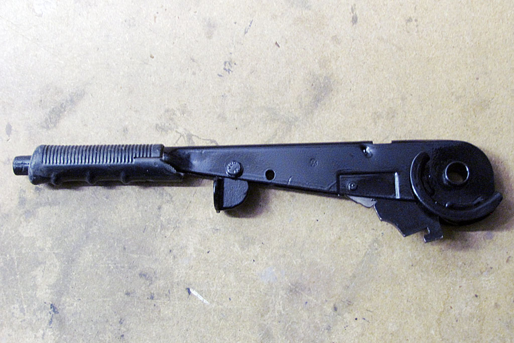
In addition, the adjustment nuts are on the back of the brake handle, which will be an elbow poker.
That will have to change. It simply sticks up way too much. But where to run it?!?!
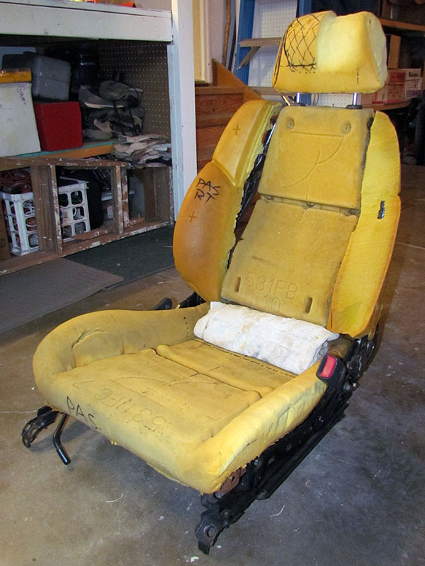
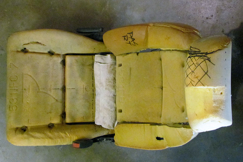
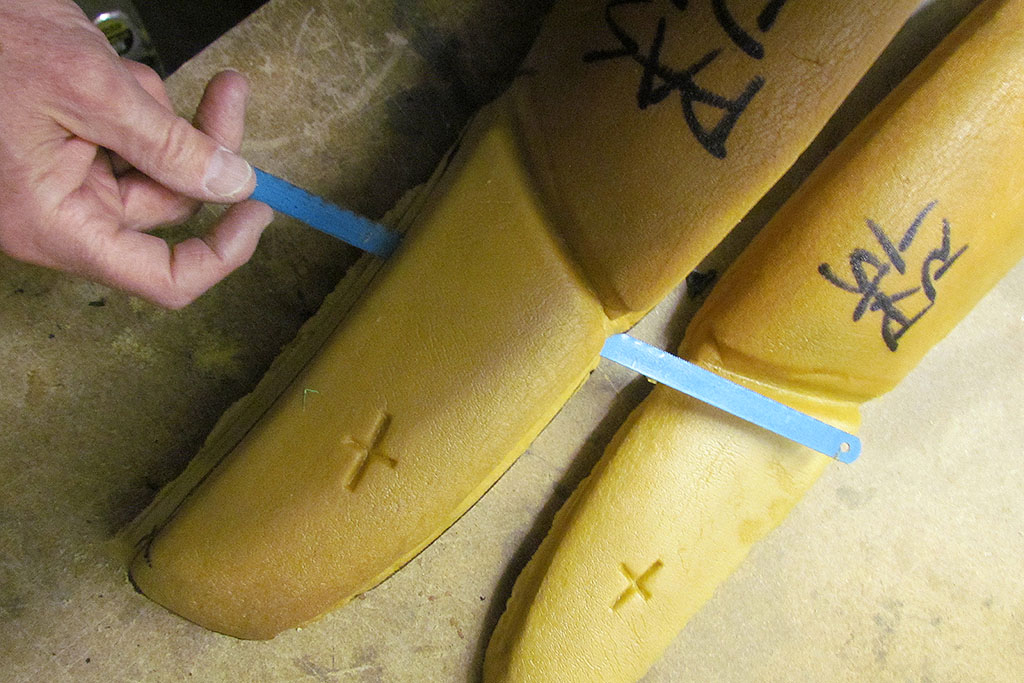
Turning back to the seats, I carved down the foam on one side to see how far I could shape it to the actual article.
These seats adjust unlike the originals, and there is a reinforcement wire in the side bolsters.
So I could only take the shape down so far.
Still, it looked closer to my eye - comfortably so. The towel filled in the lower back line.
The angles match what I calculated for the originals. The head rest did not push so far forward.
And it is comfortable (for my height) to sit in. I can't wait to take those mountain roads!
Then I took it in to the recommended upholsterer for a bid.
It was expensive for my budget, so I will wait till the car it done and then do the style touchups,
of which this will be one.
MARCH
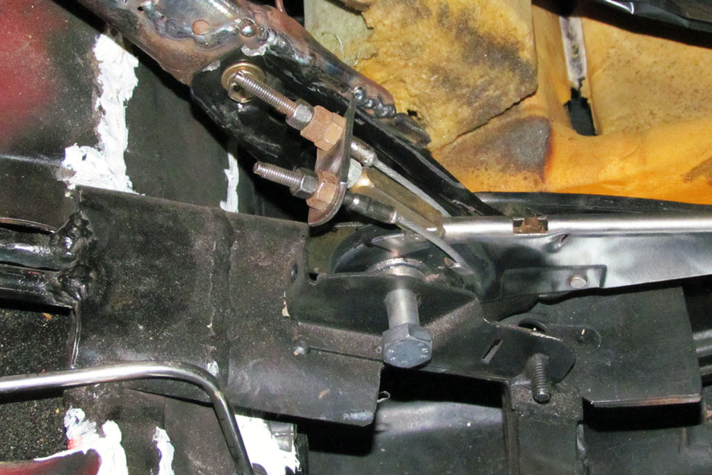
My first thought is to screw them into the base plate behind the brake handle, but the cable is not long enough.
My second thought is to add a pulley wheel just in front of where the cables come up to the brake handle,
and then have the cables screw into the base plate about midway beneath the brake handle.
That should work, but sounds more complicated than is necessary. So, how to simplify?!
My next idea is to run the cables straight along the underside of the handle.
My neighbor thinks it will still need a pulley, but I try it without one first before going to that trouble.
And SURPRISE. . . It works! But then, one of the cables pulls out of its threaded end piece.
It takes two tries using a torch to heat it and the solder in the cable cavity, but finally it holds.
Then all I have to do is balance the left and right rear wheels. Now it's the middle of March.
A call to the mechanic informs me that my engine is waiting for two owners to pick up their vehicles before any more can be worked on.
I can be patient. Do I have a choice?
On to the battery compartment. To do that means I will have to box in the front compartment.
I hope to fit a spare in there, too. Time to dig out the cardboard and start boxing it in.
The nose will have two compartments: one in front of the "firewall", or passenger compartment bulkhead,
will hold the battery and the steering coupler; and a larger one for the spare and a piece or two of soft luggage.
I mock it up with flat panels and it looks like a decent amount of space.
But then my neighbor suggests adapting the wheel well from the VW 412. If it could be made to work, it would be simpler.
Or would it?!?!
APRIL
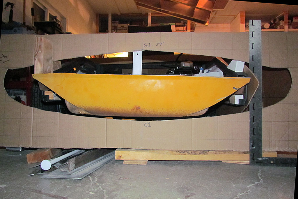
The problem is fitment, and specifically fitment in the front. Will it fit in the nose profile?
I plot out a cross-sectionat 27 inches in front of the front wheelbase, about where the front of the wheel well will be.
It does appear to fit! But then, my neighbor, who does the welding and can't believe he is saying it,
suggests to cut down the well sides to be flush with the framing members.
It sounds like a lot of work to me, but is it more than fabricating a new box? And is it worth it??
Welllll. . . I won't know unless I try. So I begin giving the well the Michaelangelo treatment,
i.e., cutting away everything that it not the final well shape.
After a three long afternoons, half of that time measuring again and again and discovering the framing members are not exactly symmetrical left to right,
I have it all trimmed down and prepped for welding, and IT FITS IN PLACE AS I PLANNED! Yup, I think I'll go with it.
The wheel well was cut out originally with no thought to using it again. After all, it was for a 15 inch wheel and not a 13 inch.
So after measuring again and again and etc., I throw a laser level on it and decide on a center line.
Then I set it to what I think are the proper heights in front and rear so it sits on a slope.
Then I mark the support frame height along the sides and begin to cut it down to that line and bend and flatten the sides so they might sit on the frame members.
That does not really work, so I cut the bent tabs back just enough to give a surface for the new horizontal filler plates left and right to rest on them.
Then I cut out those filler plates. It was the best job I have ever done with my cutting wheel. Even the left-behind holes look like I punched them out!
My neighbor is even complimenting my work. Then I cut out a template for the piece that will cover the steering mechanism.
I want to make this piece removable in case I need to service it.
That leaves the the frame side pieces. Once again I layout the contour front to back at that distance from the centerline and attach them to the frame.
This is the most accurate contour that I can establish and the one I will use when I carve the full size body.
It looks like I will have adequate space for the spare and a couple pieces of soft luggage.
One concern is how will I raise the front hood now.
I had not originally planned on a tire well there, and to raise the hood will require the well to pivot with it.
I don't think that is practical - too much weight and structure with a tire in the well.
I will have to diverge from the original car by cutting two slits into the nose underpan and making it so only the underpan from the frame to the fenders raises up.
It's not perfection, but I think it is a modest concession to practicality. After all, I want to take a road trip in the car when it's all done.
On this last weekend of April, my neighbor and I spent a 6-hour welding session and got the basic pieces of the trunk welded in.
I bought a used Mig-welder with an argon gas bottle. That made for a quicker, nicer job.
The pieces I had pre-cut needed only some slight quick trimming and together it all went.
The structure are stiff and strong and ready for the front wheel wells filler pieces next.
It was very satisfying to have that together and looking good.
And to round out the month, I finally sold the 915 transaxle on eBay. I got some working cash and some working space in the garage.
And it found a good home with a 911 owner who had trouble finding one after he was tail-ended.
Once again, I meet another car guy and make another friend thru this project.
MAY
With the major pieces of the trunk in place, that leaves the panels needed to enclose it from the wheel well.
I spend the first weekend making chipboard mockups of the panels.
>br>THEN . . . early Monday I get THE CALL!
The engine mechanic has an open bay. I race over to talk about just what he needs. 'The transmission installed' he says.
So I frantically work to finish the adaptation I need for the shift rod attachment screw and begin putting it in.
I do it twice bacause I realized the VW 412 set screw, an M10x1.25, won't work in the threaded hole we found for the shifter adaptaion.
It needs an M8x1.25. I end up grinding down a bolt to a pointed tip.
The nose cone attachment bolts are difficult to manipulate into position, but I figure out how after 45 minutes.
The gearshift is not smooth and can do 2nd and 4th, but cannot pop into 1st or 3rd.
I try to bolt in the two seats, but something has warped and I can only get three bolts in for the driver seat and not at all for the passanger!
It's late and I am frustrated and it's Tues. p.m.
Weds. May 9 we load it onto my neighbor's trailer. I make some last patterns and load up all my extra parts, and its off we go.
The word is it'll be back some time in June.
Maybe I can digitize the go-cart by then?!
Another project I wanted to work on was learning to paint those trick paints GM would put on their concept cars.
I know a man who learned how to do them working in George Barris's shop in the 50's.
We have been communicating by email. He has been telling me generally how to do the job using modern House of Kolor (HOK) paints.
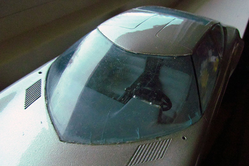
So, I decided to begin on a model. There is none of the Monza SS, but there is one of the Monza GT, but I am not ready to experiment on it.
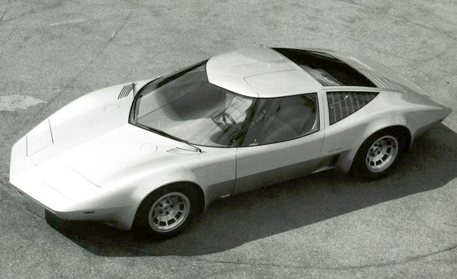
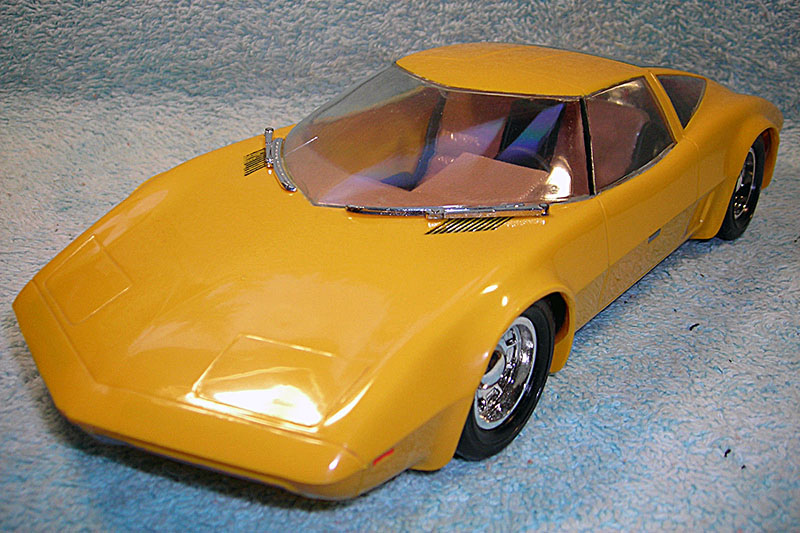
Instead, I discovered an old, 1980s Lindberg 1/18 scale Aerovette model. I've always loved that car.
It was unbelievable and oh-so desirable in the 70s when we thought GM might actually make it into the next Corvette. Alas, it was not to be.
The kit itself is surprisingly accurate except in two areas, but the interior is rudimentary lacking door panels and the rear bulkhead.
There is a wankel engine that very simply represents the one used. But they for some reason did not angle in the front fenders ahead of the front wheels.
And the instrument cluster housing is too big and boxey. I did not want to detail this model out, but I could not live with those errors.
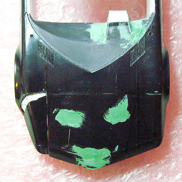
So I added interior panels and the bulkhead, reshaped the cluster housing, and then cut and puttied heavily the fender realignment.
I lost time trying to polish the windows and almost destroyed them. Oh, and I added a panel across the underside.
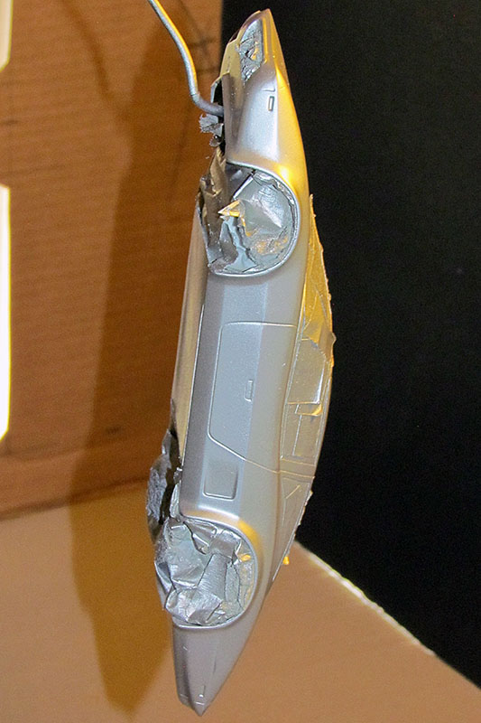
I masked it up and I was ready to paint.
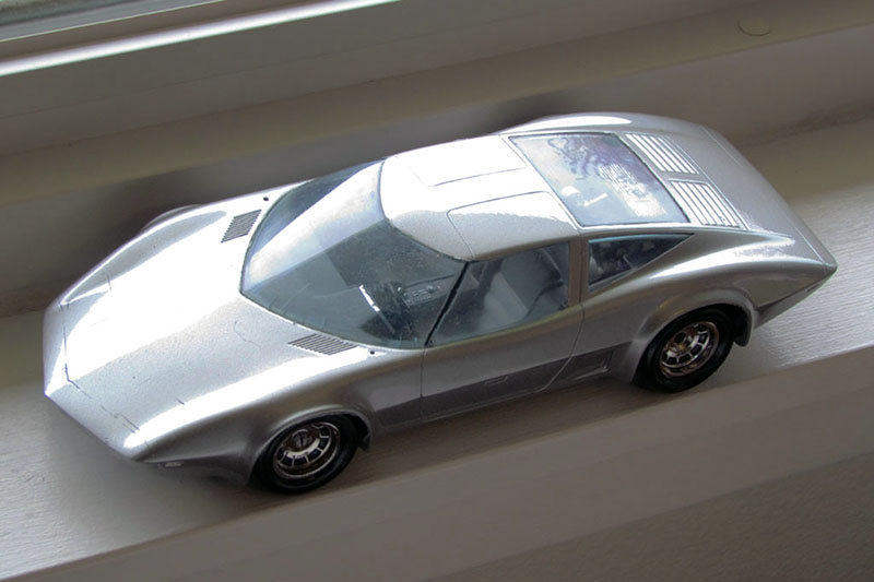
Although it looks like it is only silver, it is really a silver base plus a pearlized silver overcoat lightly applied.
When dry, an HOK clear coat is applied overall.
The silver ended up very granular looking, but the clear coat shocked me by drying nearly completely smooth.
I had no desire to sand it all down to redo the silver. It was good enough for a first try. There will be future trials.
JUNE - JULY
I learned that the mechanic experienced a family emergency that closed his shop for the month.
So I turned to catch up on things that did not get done before the chassis left.
The multifinger pulse generator for the Hall effect sender for the speedometer mounts on the driver-side CV joint.
But the mounting holes are larger than the diameter of the CV bolts, and it will not center on them.
So when it rotates it wobbles and will either strike the sender or vary in distance so as not to give a good signal.
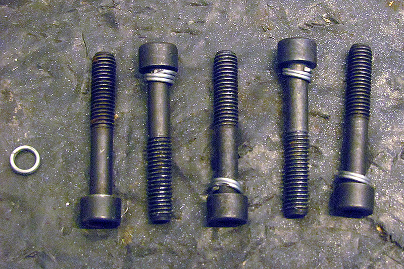
Looking for spacers to fill the gap, I settle on using a spring. Two or three coils will work to fill and center the unit.
I use a Dremel cutoff disc to cut off the pieces I need, but getting them past the threads of the bolts is another matter.
I end up drilling a hole in a U-channel and with a hammer tapping them on. And violá - it works!
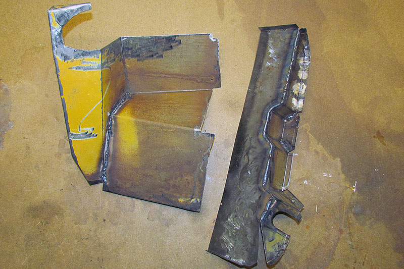
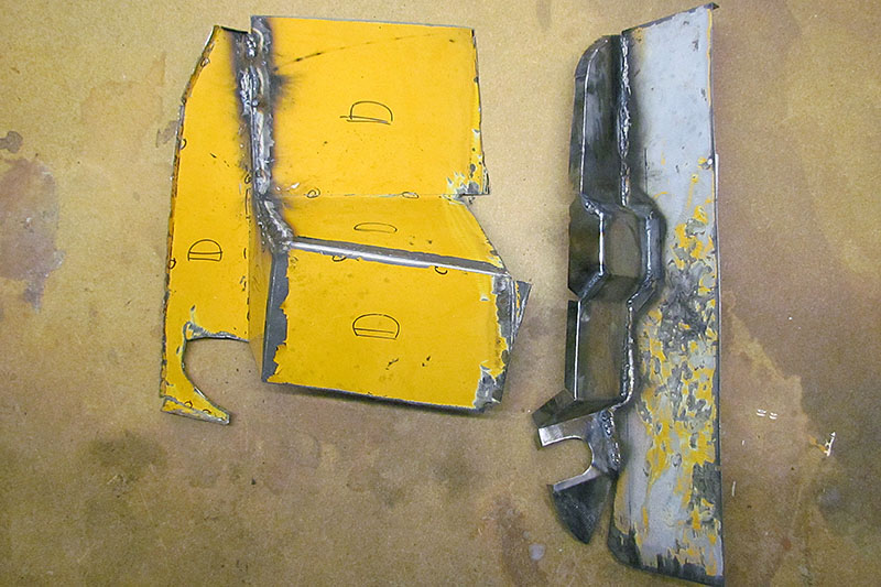
That done, I turn to completing the sheet metal work to enclose the trunk.
The big pieces are the cover for the steering unit, and the cover over the front suspension springs.
I had made templates before the chassis left, so now it was simply to cut them out, fold them up, and weld them.
And that's what I did. I did the straightening, folding, and bending on my vise, and my neighbor did the welding.
Next up was the form I needed to shape the gas tank to conform to the body of the Monza.
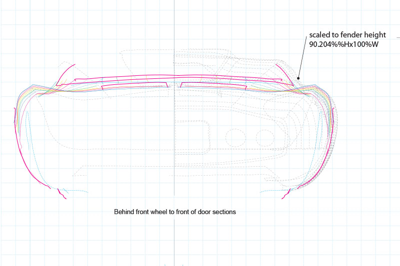
Using my best contour plan, I took a section from behind the front wheel and another in front of the door.
Then I cut out and glued sheet corrugated cardboard, to represent the thickness of the body shell, onto the contours.
When the chassis comes back, I will make the patterns for the tanks in situ.
AUGUST - OCTOBER
The mechanic is back to work but he is backed up into September just to catch up.
He understands my position, that I am under no deadline and so my job is his lowest priority.
That is okay with me - I still have other things to do.
By the end of September, he did get the engine installed. The next step is to get it running.
And so I come to my next biggest step before making the body . . . DIGITIZING THE CHEVY JR GO-KART BODY!
SIDEBAR: History of the Monza Jr.
Here is a brief history of the Monza Jr. go-kart.
The best history I have found is here.
It started out as a gift for Bill Mitchell's stepson, combined with an advertising purpose of a promotional item to pay for building it.
Later, due to its popularity, it was sold to all-comers.
The first one was unique and most like the actual car in details. It was a custom red similar to GMC Cardinal Red. A 2nd metallic blue kart was made for the son of Chuck Jordan (Mitchell's right-hand man and heir-apparent).
It was one of the promotion bodies, and was customized by Larry Shinoda to resemble the Mitchell kart.
The promotional bodies dropped the vents and windshield, changed the emblem on the nose, and early in the production run lowered the rear deck behind the seat and around the engine.
They were painted a solid red, perhaps a Corvette Ember Red.
The consumer version was renamed the Chevy Jr., dropped the nose badge and was painted orange-red with a white horizontal nose and tail stripe or metalic blue with white stripes, or white with a blue nose stripe.
front-to-back thin white racing stripes were also applied as another decoration style.
Prices vary, but a Monza Jr in good shape today will cost you around $2500 to $7000 - when they are available.
Unlike for the real car, I CAN touch and even make marks on my go-kart body. And so I do.
The go-cart is real close to 1/2 the size of the real car - surprisingly!
So to match my three-inch grid I used on the car drawings, I make lines 1-1/2 inches apart on the go-cart.
I will not go into how I laid them out - there are multiple ways, but I used a white paint pen from Hobby Lobby that is water-proof but alcohol-removable.
It took about six weeks of grabbing free time to make all the lines.
I ended by using chalk on the ridge lines using the flat chalk surface to more easily follow the ridge center line.
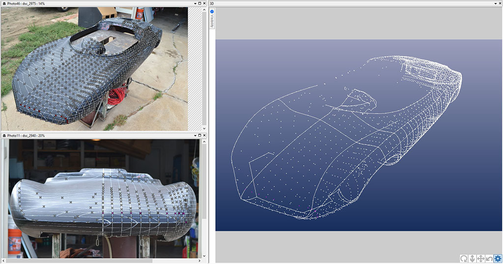
What this allowed me to do was, in the space of a few minutes, take as many pictures from as many angles as I wanted.
Then in a longer session one evening, I made some hard measurements to points identifiable in the photos.
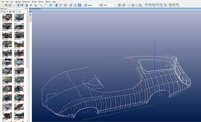
All this would be entered into the Photomodeler program, and once again, I would generate a 3D file of points, lines, and curves.
All the digitizing was done by the end of September.
What I hoped and expected to find was a close match of contours on the nose, the entire side outside of the fender ridge line, and the rear kamm cove.
I knew not to expect the area between the fender ridge lines to be usable because of the necessary distortions required to fit in a scale, twice-life-size person.
The comparisons were, at first blush, disappointing:
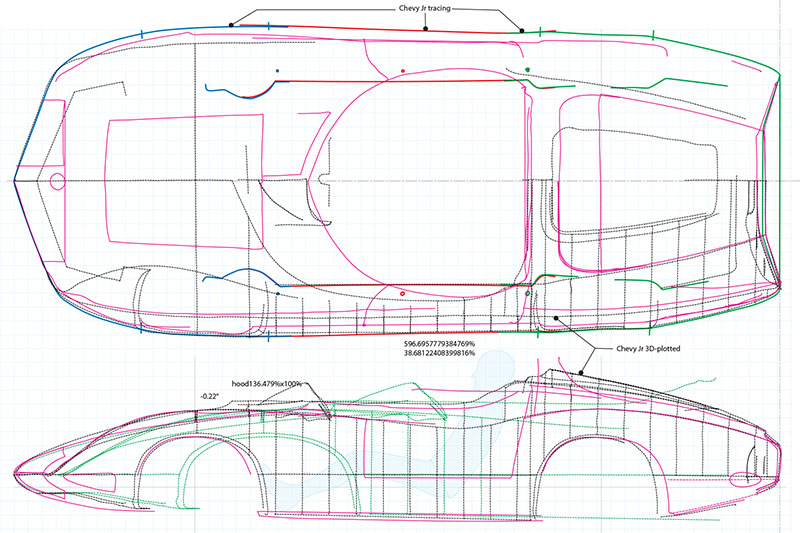
1) The fender ridge line from side view is a near dead-on match . . . but not from top view.
The midpoint of the body is not as pinched in as the real car, and so the fender ridge does not pinch in as much.
2) The kamm cove is good overall, but . . . is proportionally taller than on the real car.
3) The wheel wells are positioned just about the same on the side view, but . . . the rear wheel well opening is not as wide (front to back) as the real car.
4) The nose V-shape in the top view matches the real car. Yay!
5) From the front or rear view, the body contours outside of the fender ridge, align when the ridge lines are lined up
and are scaled to the height as measured from fender ridge to the bottom of the pan, but bulge out more than on the real car.
What can I use from that effort?
The nose shape discrepancies I can ignore. The kamm cove can likely be scaled to match. The wheel wells I will have to play with.
The outside body contours are my challenge. I hoped to use that to fill in missing detail from the real car.
We shall see what disproportional scaling results in.
I am now in process of locating a multiangle spectrophotometer to read the color of the 1964 New York World's Fair Corvette concept car,
and to prepare to visit the GM Heritage Center to do some research on the history of the Monzas . . . and now, to retake some new measurements.
NOVEMBER
I began preparing for my next research trip. I want to return to the GM Heritage Center to take more photo measurements and do archive research.
I also want to visit The Henry Ford Museum and the Pierce-Arrow Museum.
And maybe even try to interview some retired GM engineers and designers.
Researching original colors it a big goal. There are a couple of examples I found on the web.
I am in process of getting permissions. In the mean time, I am collecting early '60s GM paint chips and samples.
One possibility is that the Monza SS was originally painted a Fire-frost Red, a color only used on Cadillac Eldorado Biarritz's.
But the color changed each year.
Bill Mitchell, I am told, would paint show cars in that color occasionally to test the market for a color to be introduced a year or two later.
But I can find NO chips of the special Fire-frost colors - they are listed by code only on the chip charts.
My designer contact believes his recollection was that the Monza SS was originally painted a Corvette Rally Red.
That could very well be. The best color photos I have do not convince me it is a metallic or trick paint.
But by '64 it looked very close to the 1964 New York World's Fair Corvette show car.
Well, I need to learn how to examine those metallic, tricoat, candy, and trick paint jobs so I will be ready to examine the real articles.
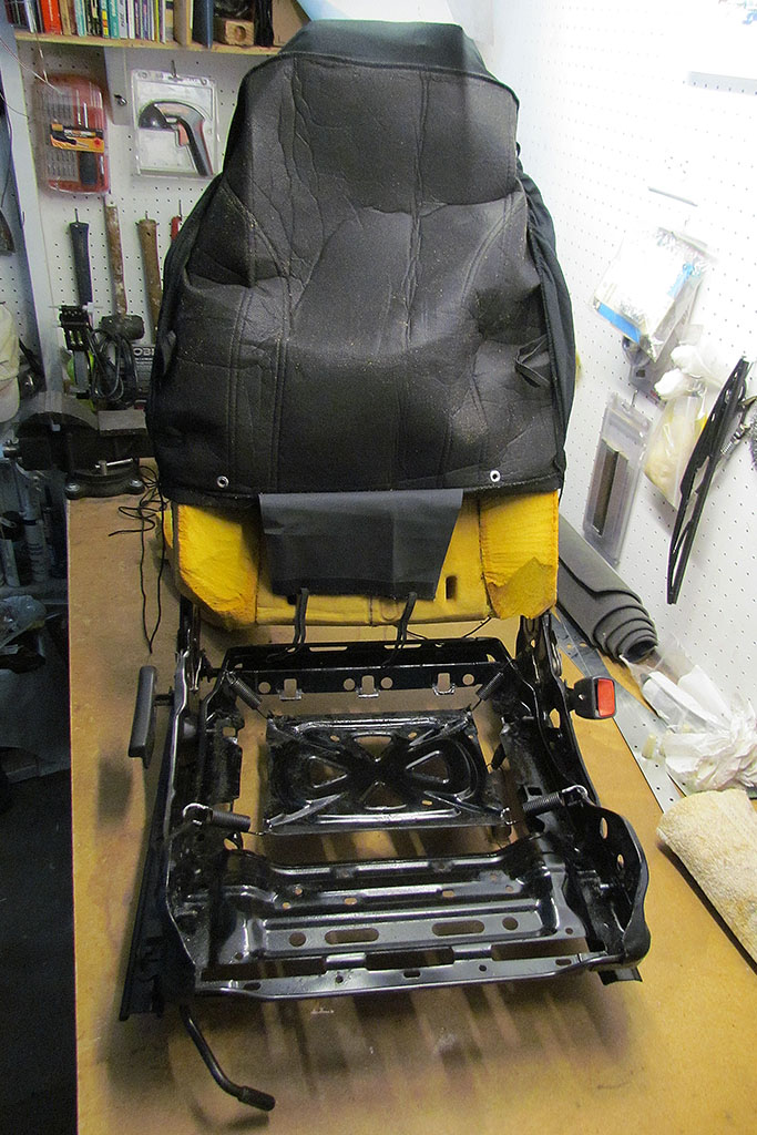
I took a break to returned to carving the passenger seat and attempting to cover it.
I decided on a cheap seat cover as an interim solution until I can afford to properly upholster the car after it is all assembled and running.
The goal is to approximate the seat shape on the Monza SS.
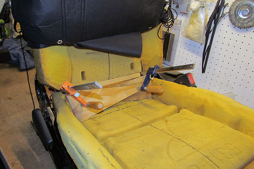
So I carved down the bolsters and gave them more of the seatback shape.
I glued in an upright piece on the seat bottom to fill the space behind the buttocks.
Then I trimmed down as much as I could the seat bottom bolsters, while still retaining enough to keep the buttocks from slipping sideways on turns.
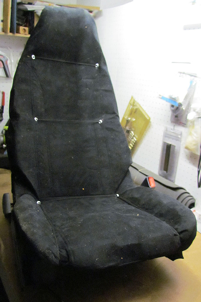
Then I worked out a lacing pattern to use a single length of cord to loop back and forth thru the eyelets I added to the seat cover.
Does it work? Well, I will test it when it goes back in the car.
And at last! The mechanic is able to work on installing and starting the engine in the chassis!
And an automotive designer in India is cleaning up my digital files and creating a real 3D model of the Monza SS!
Check out 2019 for more progress!
MORE SPECS
Battery:
Group 42-1, 6-7/8"x6-7/8"x9-1/2"
SIDEBAR: History of the Monza Jr.
Here is a brief history of the Monza Jr. go-kart. The best history I have found is here.It started out as a gift for Bill Mitchell's stepson, combined with an advertising purpose of a promotional item to pay for building it. Later, due to its popularity, it was sold to all-comers.
The first one was unique and most like the actual car in details. It was a custom red similar to GMC Cardinal Red. A 2nd metallic blue kart was made for the son of Chuck Jordan (Mitchell's right-hand man and heir-apparent). It was one of the promotion bodies, and was customized by Larry Shinoda to resemble the Mitchell kart. The promotional bodies dropped the vents and windshield, changed the emblem on the nose, and early in the production run lowered the rear deck behind the seat and around the engine. They were painted a solid red, perhaps a Corvette Ember Red. The consumer version was renamed the Chevy Jr., dropped the nose badge and was painted orange-red with a white horizontal nose and tail stripe or metalic blue with white stripes, or white with a blue nose stripe. front-to-back thin white racing stripes were also applied as another decoration style. Prices vary, but a Monza Jr in good shape today will cost you around $2500 to $7000 - when they are available.
The Build--2018
January
1st ROW
(L) A peek inside at the valves - they both looked closed.
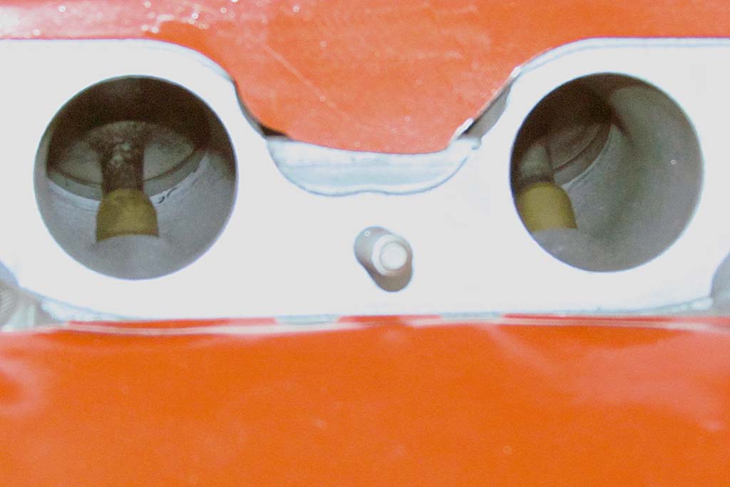
(C) Confirming TDC - rocker arm positions for cylinder 2 (left) and 1 (right).
At TDC, #1 rocker arms are both holding steady in the same postion and don't move when the engine is rotated.
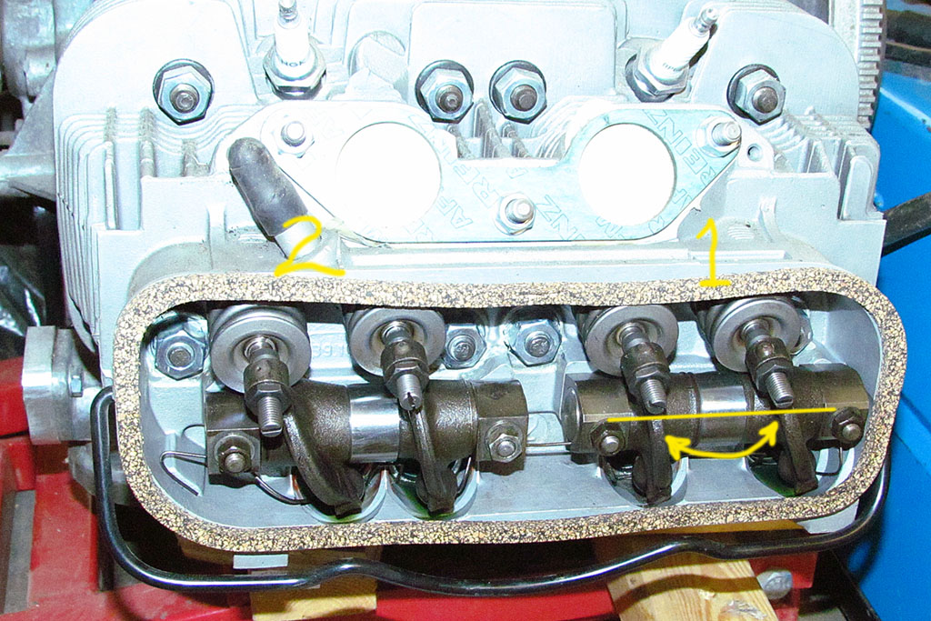
(R) And rocker arm positions for cylinder 3 (left) and 4 (right).
When #1 is TDC, #3 rocker arms have moved in opposite directions.
But at the moment of #1 TDC, #3 rockers "overlap", or "twaddle". Yes, that is the word for it.
That means #3 rockers are in the same postion. They are and rotating the engine reveals their opposite movement.
2nd ROW
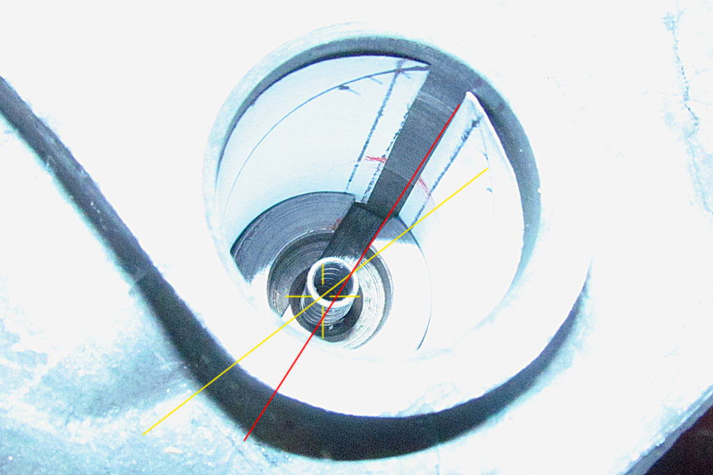
(L) Checking the angle of the distributor drive key . . .
(C) But the dizzy won't insert when the rotor aligns to the alignment mark on the distributor edge.
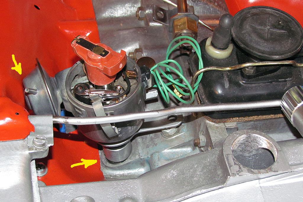
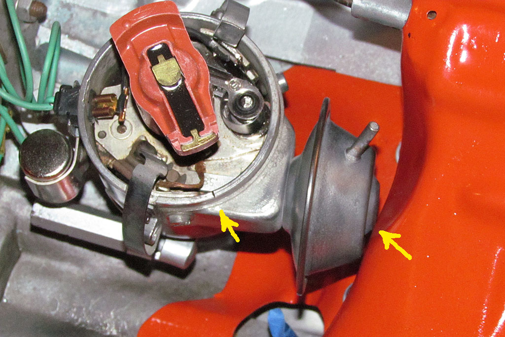
(R) The engine tin is where the vacuum can wants to be.
1st ROW
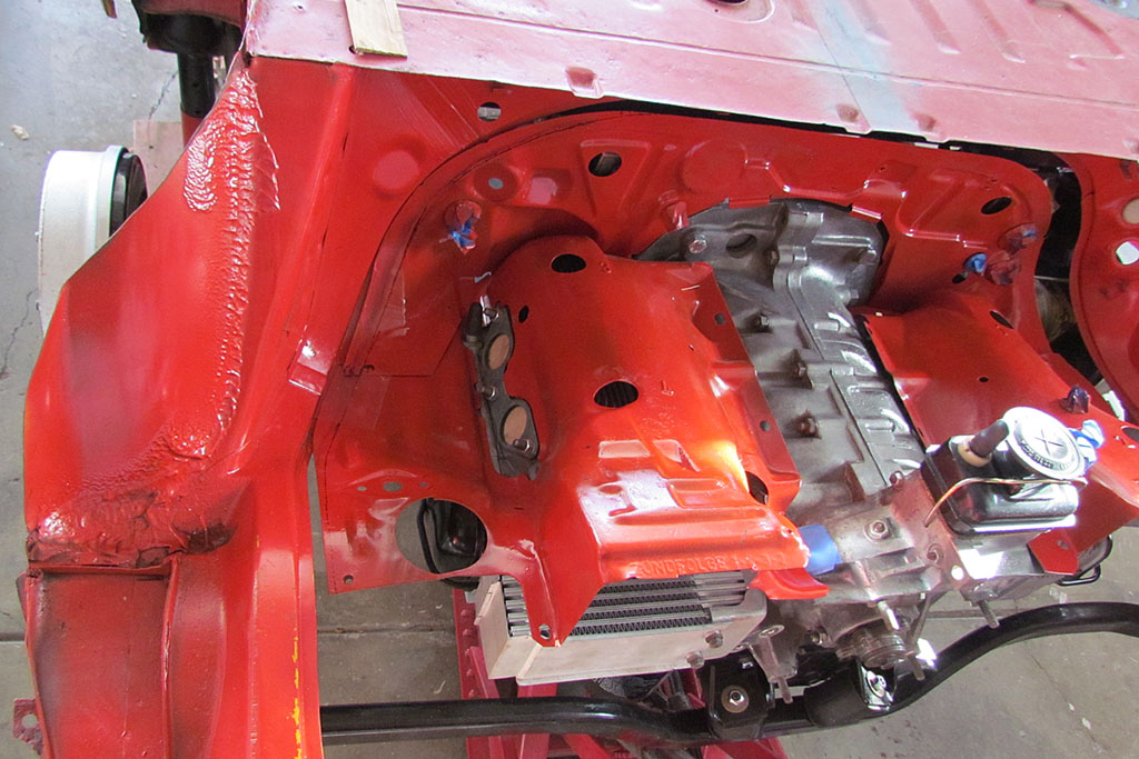
(L) Here's the problem with the engine tin when it shifted after the engine was centered.
The answer is to cut about one inch off the driver side, and add some to the passenger side.
(C) Side view - upper cooling tin in place and attached to the block and fan housing
(R) Front view - cooling tin
2nd ROW
(L) The rest of the top tin in place
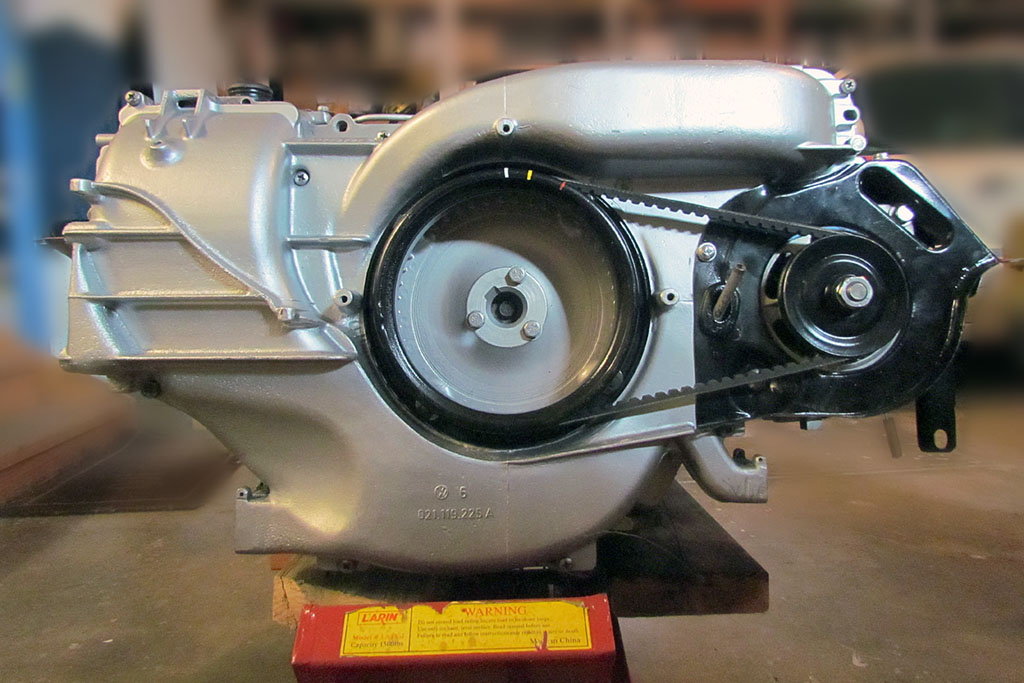
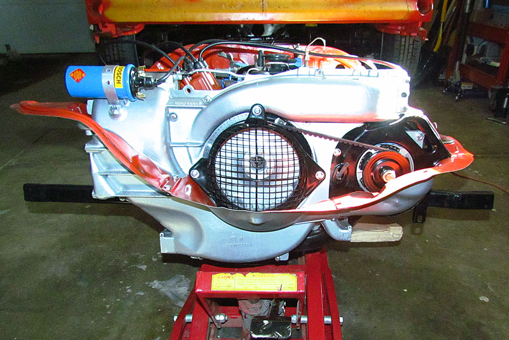
(R) Straight-on view of the fan housing
FEBRUARY

1st ROW
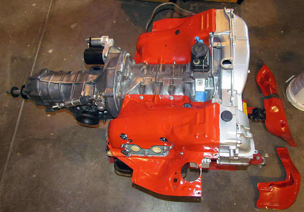
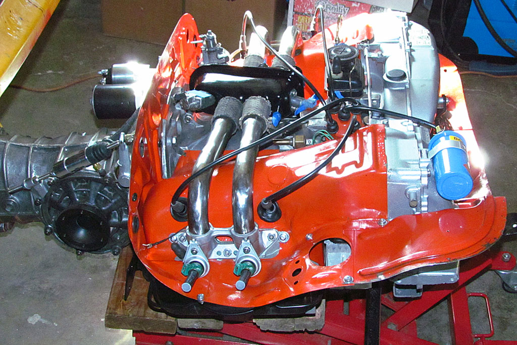
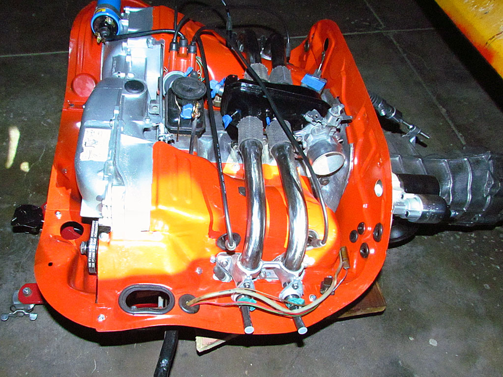
(L) The engine as far as I took it - left side . . .
(C) And right side . . .
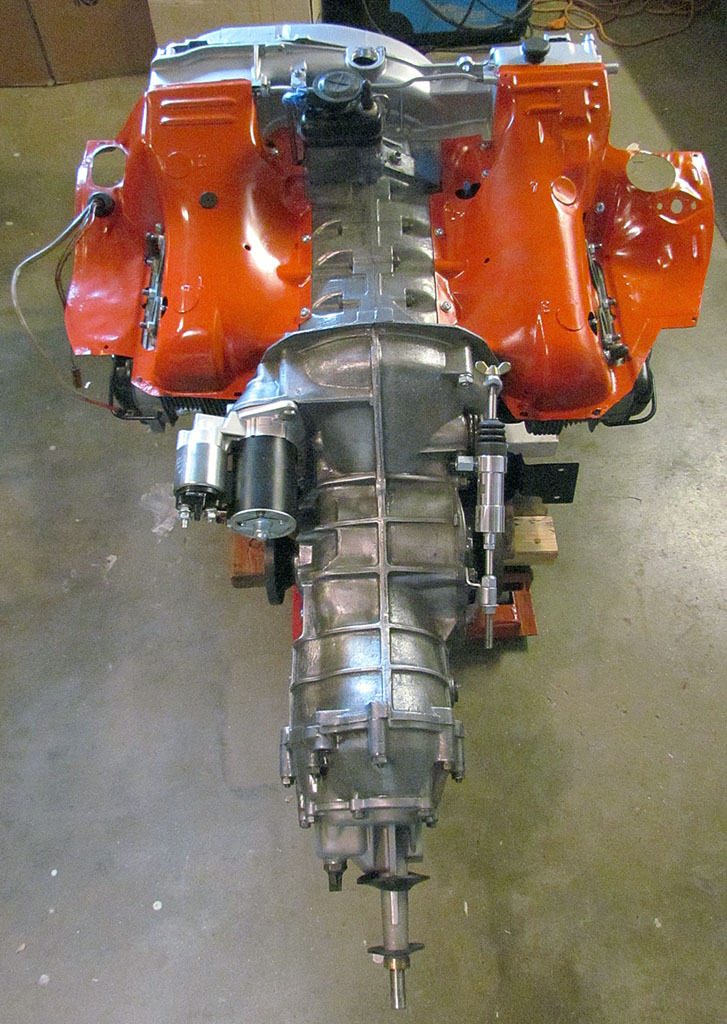
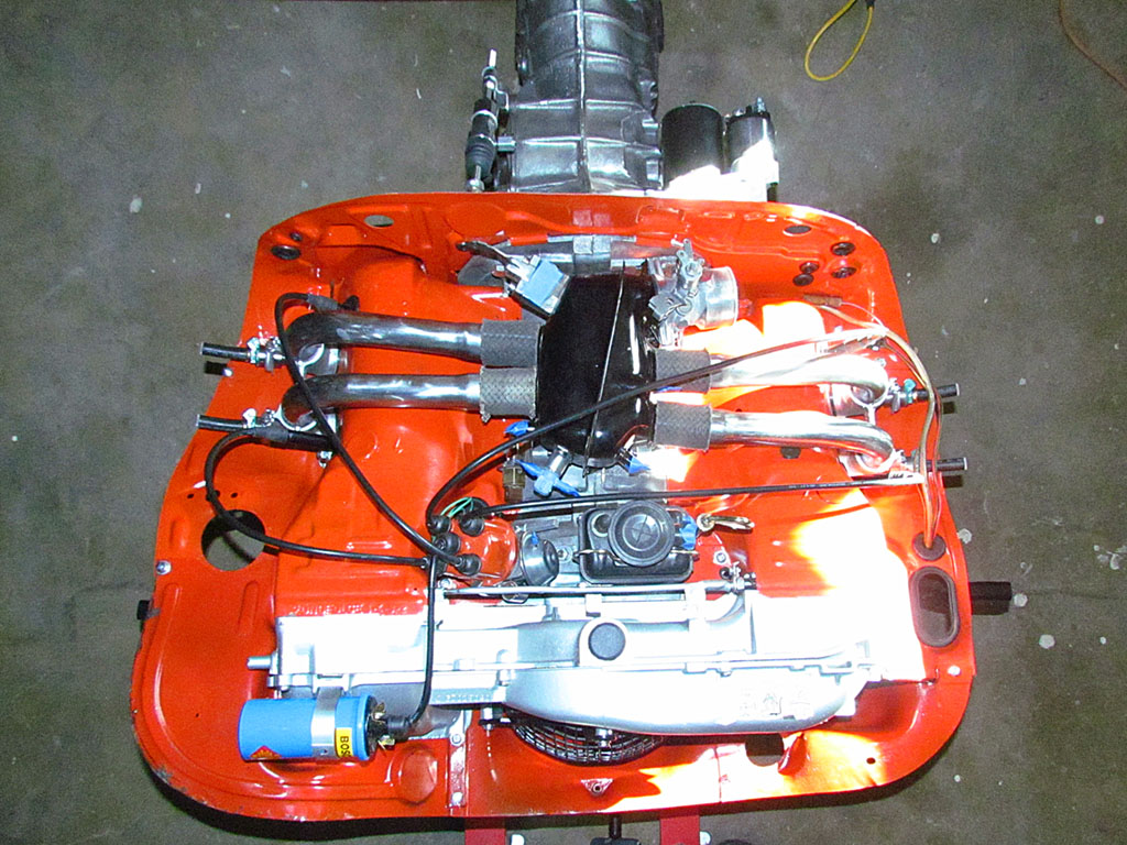
(R) Top view from rear . . .
2nd ROW
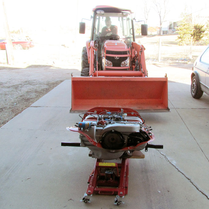
(L) And a view from the rear . . .
(C) One way to lift a 200 pound engine without a hoist.
(R) Padded for its trip to the mechanic

1st ROW
(L1) 3/4 front view: left is before, right is after shaping.
Note the towel, which completes the seat back line, but allows the seat back to tilt forward.
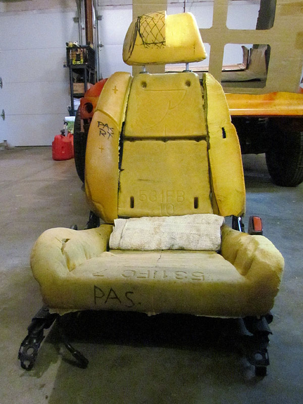
(L2) Front-on view: same left/right difference
(C) Headrest 3/4 front view showing how much it was taken down
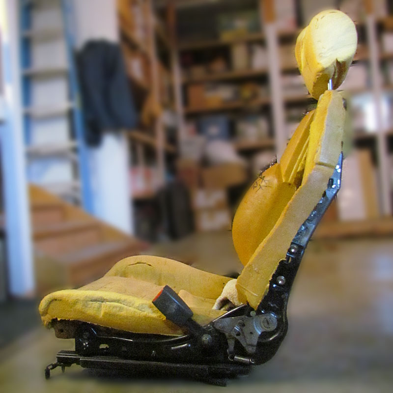
(R) Side view illustraing how much was removed from the bolsters
2nd ROW
(L) And a top-down view
MARCH


1st ROW
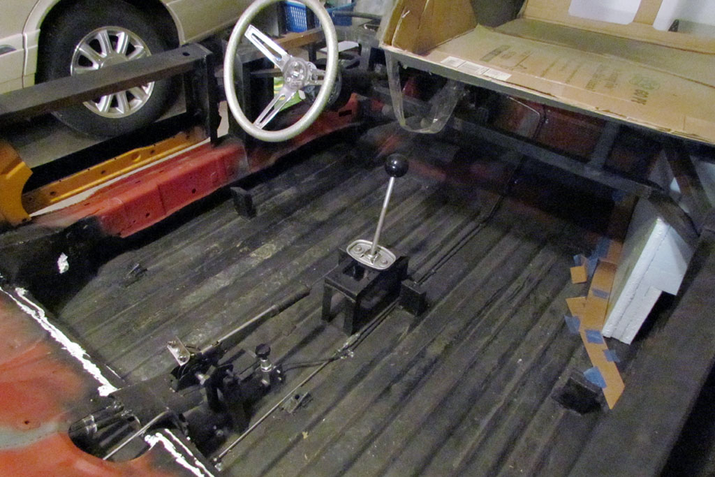
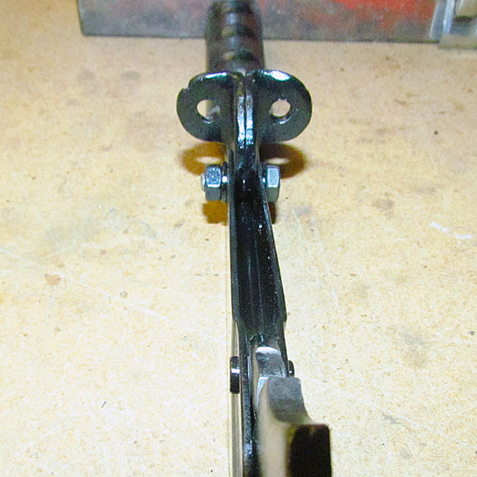
(L) A view of the interior and the safety brake
(C) Close-up of the safety brake adjustment. It's an elbow-gouger.
(R) The modified safety brake handle
2nd ROW
(L) Close-up of the new adjustment position. The pieces freely pivot.
(C) Another view looking back-to-front along the brake handle
(R) Before (right) and after (left) heat exchanger repair. Note the stainless steel wire mesh pieces.
APRIL


1st ROW
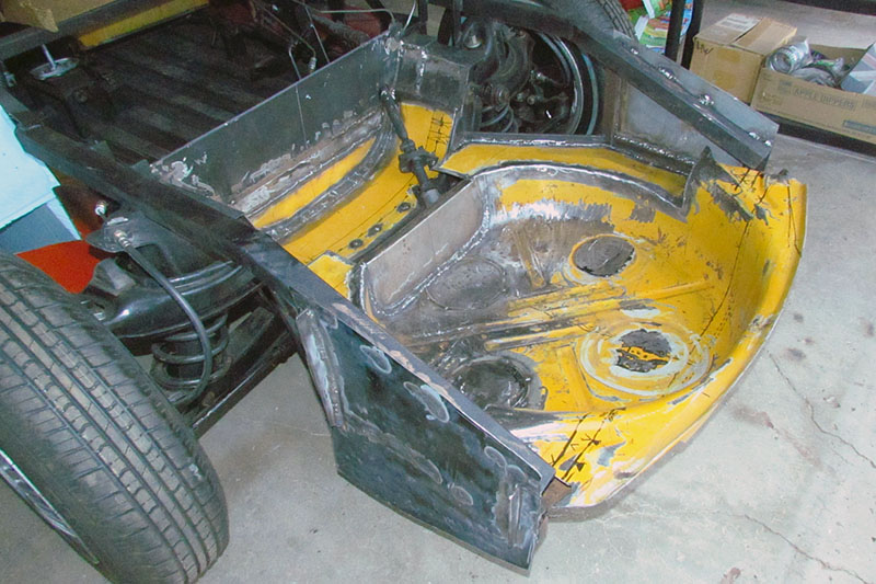
(L) I began by simply boxing in the battery well and the spare tire well. I expected to employ plain flat sheet metal. And it works.
(C) First test of using the VW 412 spare well. Yes, it will fit and is strong, but it wastes space.
(R) This view shows the necessary angle to fit within the nose profile.
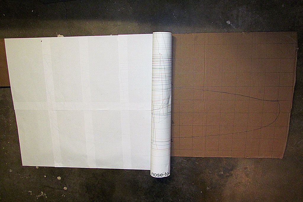
2nd ROW
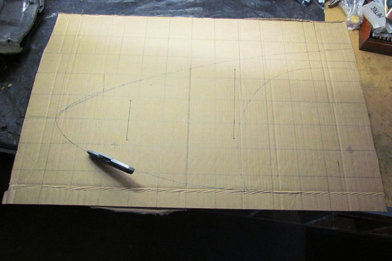
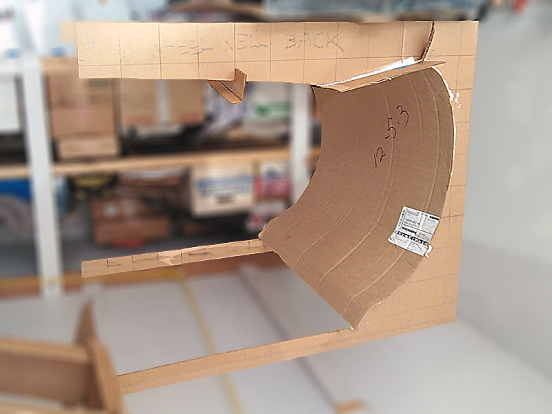
(L) I need a cross section at the forward end to accurately check fit inside the nose.
I begin by transferring a full-sized line drawing to cardboard.
(C) To do so, I trace the line by punching holes along the contour, pencil it in, and cut it out.
(R) The contour correctly positioned - and it clears!
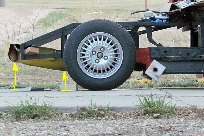
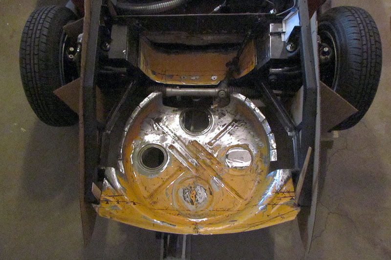
3rd ROW
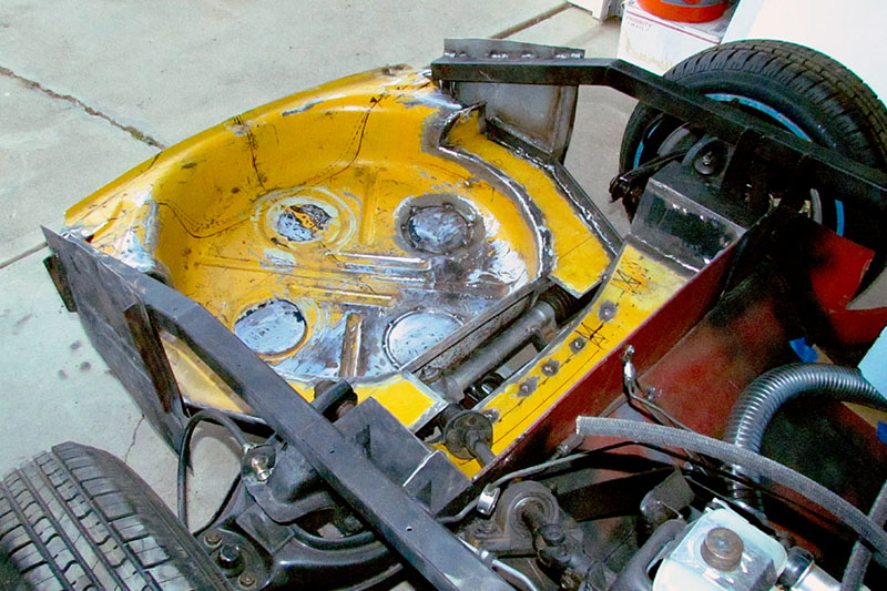
(L) This view better shows the clearance. The yellow arrows point to the area of greatest concern.
(C) Tire well sitting upright and straight-on to the laser level to establish the center line and horizontals
(R) The trimmed and cleaned up tire well with the driver-side frame template in place
4th ROW
(L) Cutting out the contour for the frame side. It was laid out the same way as above.
(C) The frame contours in place. That should pretty accurately define the space.
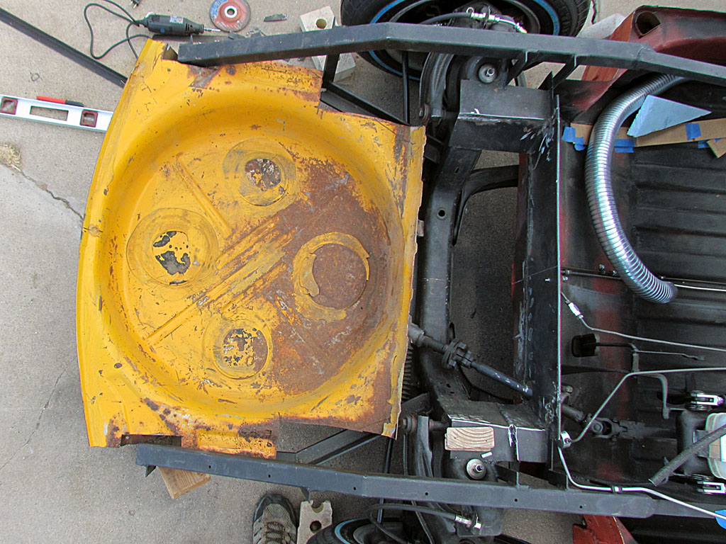
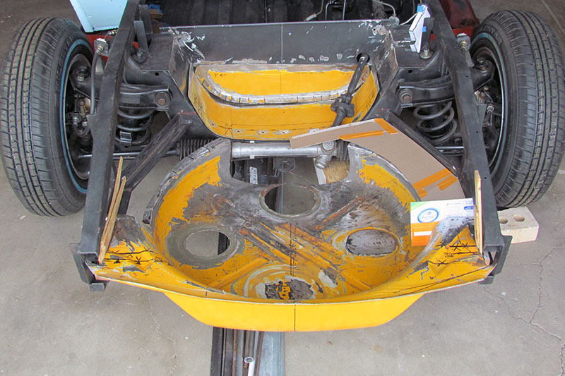
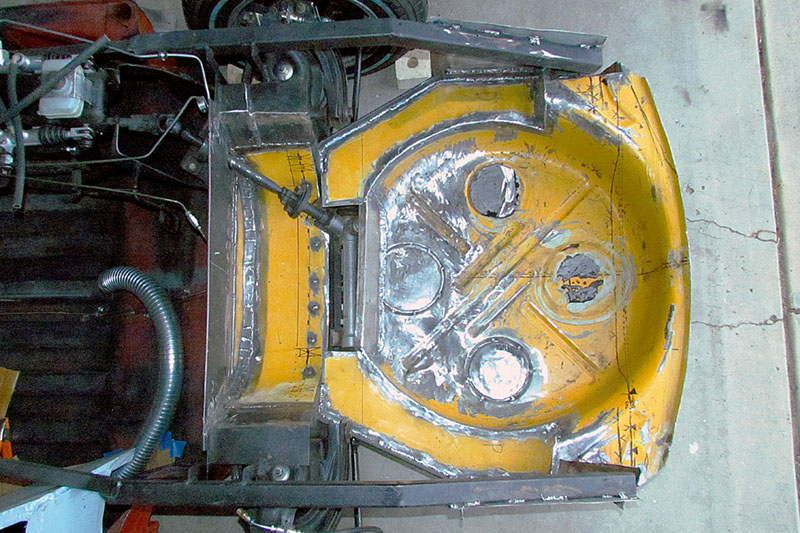
(R) A look-down view. The battery well is next to the "firewall" at top. The steering mechanism is visible.
I have a couple of templates to box it in and keep the road dirt out of the nose compartment.
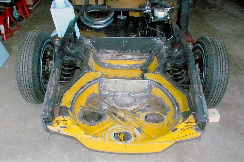
5th ROW
(L) Head-on view of front well welded in
(C) Front overall view
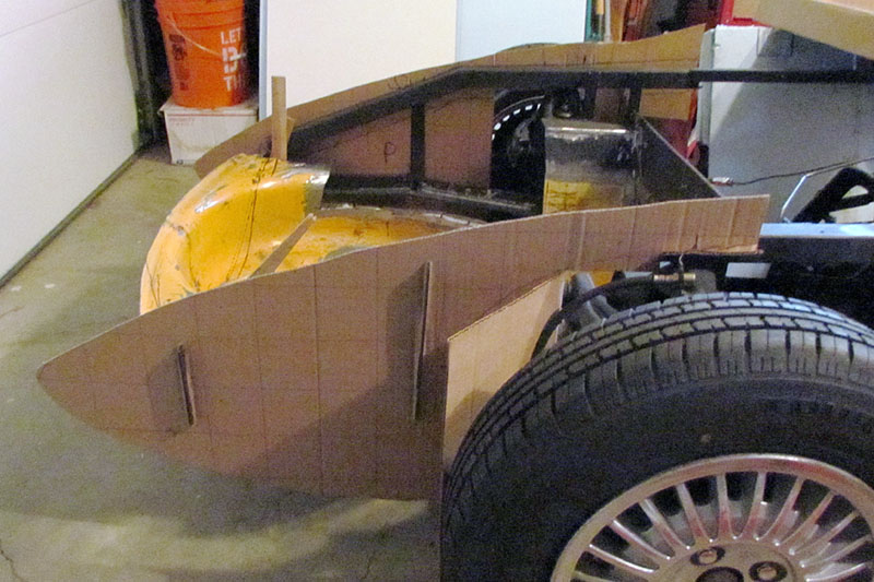
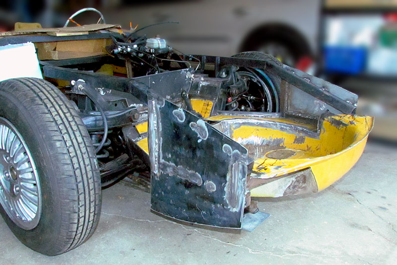
(R) From the passenger side showing contour side plates. they have been cut down 1/2 inch from the actual contour.
6th ROW
(L) Side view showing more of the compartment space
(C) Driver side view from behind. Note the space for the steering gear.
(R) A look-down view. The battery well is next to the "firewall" at the left. The steering mechanism will be accessible.
MAY
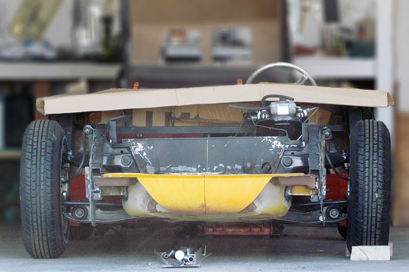
1st ROW
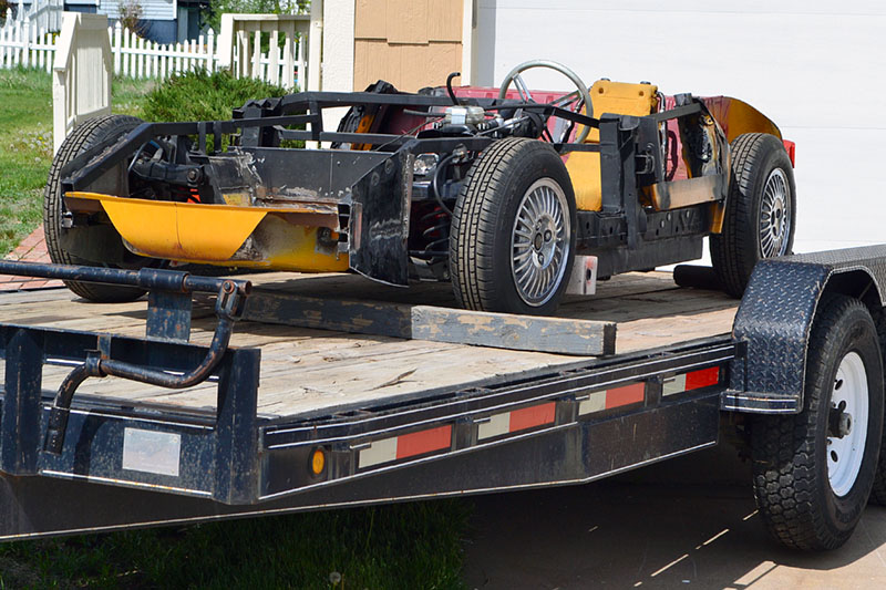
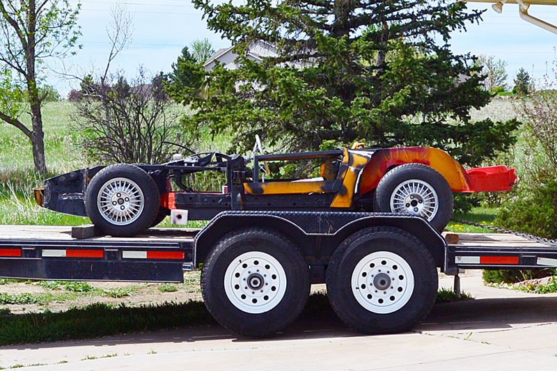
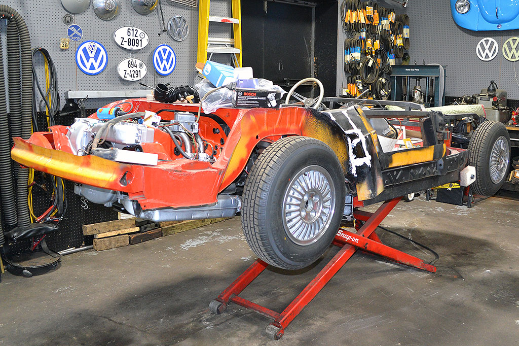
(L) Strapped down and ready to go.
(C) The frame is suggesting the body shape.
(R) With the transmission in place on its mounts.


1st ROW
(L) The original car, XP882 4-Rotor Corvette prototype - pre-Aerovette
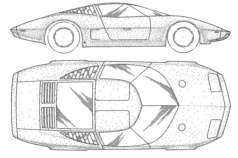
(C) Elevation views from the patent drawing. Note the top view nose angle.
(R) A nicely made out-of-the-box model of Lindberg's 1/18 scale Aerovette
2nd ROW
(L) Here is the major errors: the nose angle (left:corrected, right:original)
and the instrument cluster, here modified (compare to the yellow model's)
(C) My indoor paint booth set up with an exterior box fan + furnace filter
(R) In the paint booth with the HOK silver coat applied
3rd ROW
(L) Nearly finished, showing the gloss coat
(C) Another angle to show the gloss coat. It's hard to the touch, unlike regular model gloss coats
(R) A close-up of the gloss. Note the rough finish to the silver. I think it was too dry going down.
June - July


1st ROW -JUNE
(L) The pulse generator ring for the speedo Hall sensor. Note the bolt spacers to center it.
(C) My guide to hammer the spring spacers onto the bolts. They would not screw down.
(R) The CV bolts ready to screw in
2nd ROW - JULY
(L) Template and cutout for covers to the steering box and spring mount (D=driver side)
(C) The parts bent and welded - outside
(R) The parts bent and welded - inside
3rd ROW - JULY
(L) Body shell contour to form the gas tank to for maximum volume
August - October


1st ROW - AUGUST-SEPTEMBER
(L) The original Monza SS Jr.
(C) The blue 2nd Monza SS Jr.
(R) The production-run, Monza SS Jr. promotional model. Note the new nose emblem but still retaining the high seat back.
2nd ROW - OCTOBER
(L) The Chevy Jr. Rupp consumer model in orange-red.
(C) The same version in blue.
(R) And the white version used for the "Safetyville USA" course. The photo was from the 2004 Corvair Convention, Lexington KY webpage.
3rd ROW - AUGUST-SEPTEMBER
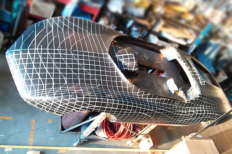
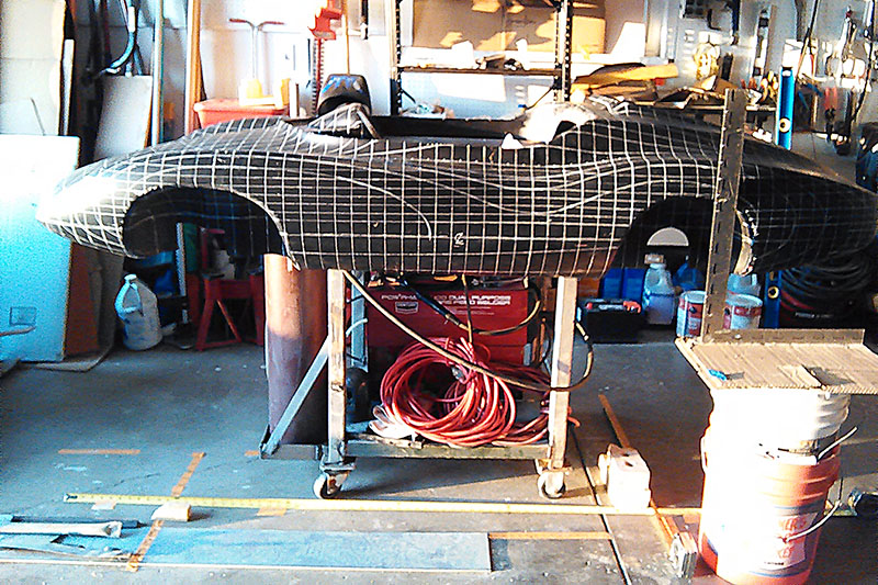
(L) Chevy Jr body with contour lines painted on, approx. 1-1/2" or 3/4" spacing
(C) Side view
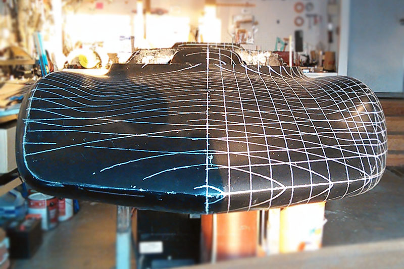
(R) Front view. Ridge lines are chalked on.
4th ROW - OCTOBER
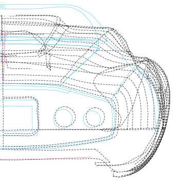
(L) Orthographic side view of digitized body in Photomodeler
(C) Isometric view, some contour lines drawn from point to point
(R) Example of cross-referencing between photos. Note magenta Xs in each view.
5th ROW - OCTOBER
(L) Comparison #1 fender ridge (magenta = real car, black = go-kart)
(R) Comparison #5 body contours (magenta = real car, gray = go-kart)
(C) Comparison #2 kamm cove (cyan = real car, gray = go-kart)
November
1st ROW - NOVEMBER
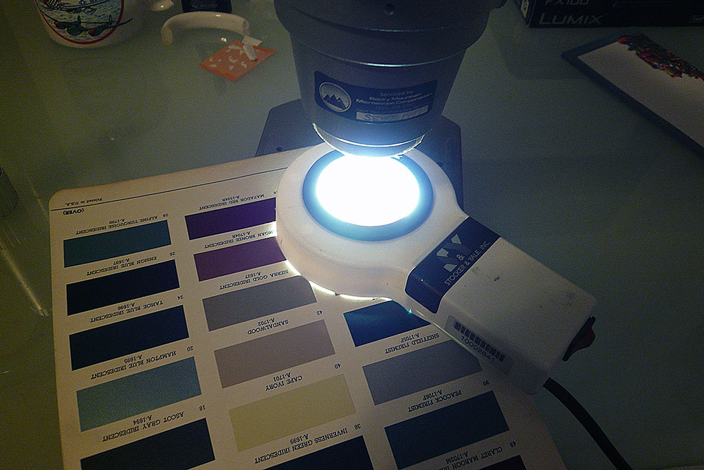
(L) Here's a "macro-scope" (my term) I use to examine the chips close up to learn how Fire-Frost is different from metallics.
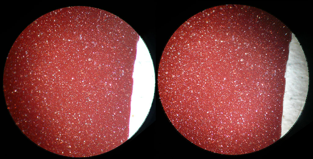
(C) And here is a stereo of the 1965 Crimson Firemist chip.
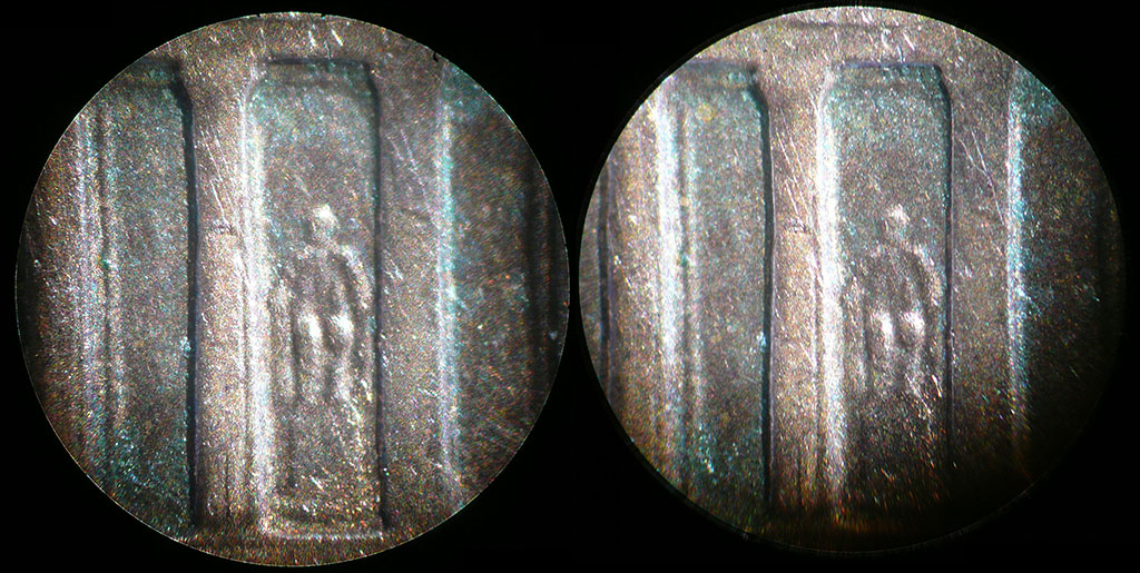
(R) For comparison, here is the obverse of a penny showing Lincoln's statue in the Lincoln Memorial.
2nd ROW - NOVEMBER
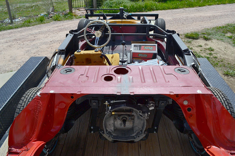
(L) The chassis in its work bay
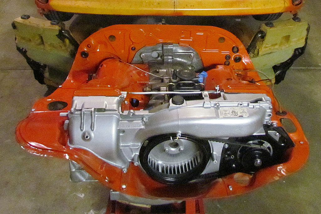
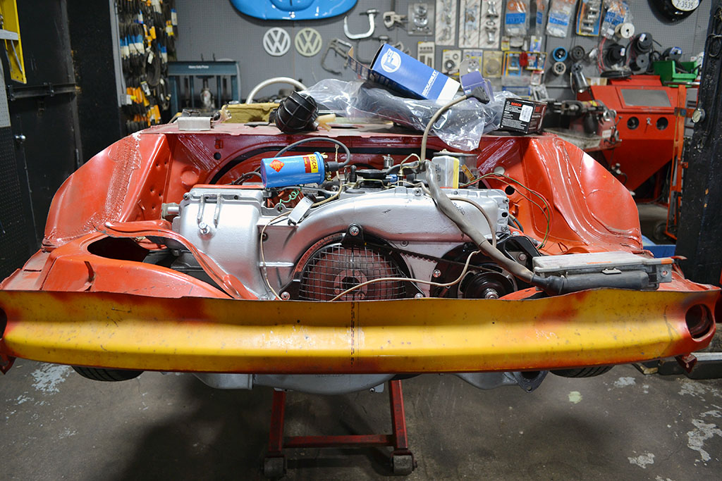
(C) The mechanic confirmed the engine is centered. The tin difference is between the 412 engine bay and the '77 VW bus tin.
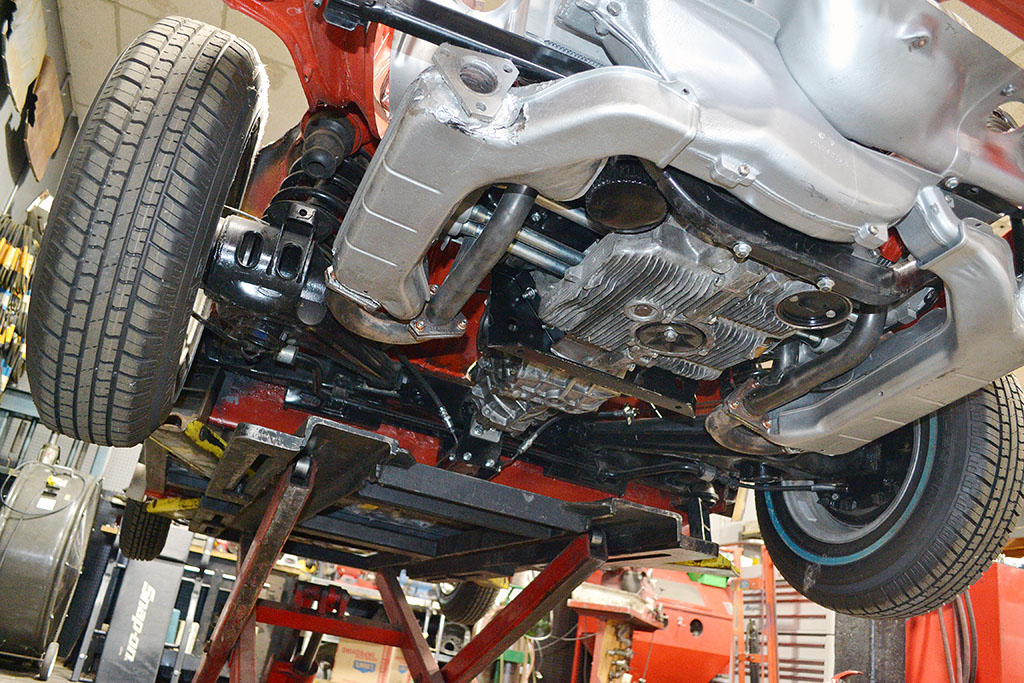
(R) The engine installed viewed from below. Love those heat exchangers! It needed a revised bell housing mount to clear the tin panel between the engine and the transaxle.
3rd ROW - NOVEMBER
(L1) Carving foam is not a problem. A hack saw blade and a serrated hand plane is all I needed.
(L2) The frame all painted and ready to cover.
(R1) Glueing down the the lower piece to support the buttocks.
(R2) The seat cover fitted and laced.