Contact: Rich Kurz Page content last updated Feb.14, 2024
The Construction Diary
2023
JANUARY
With a new garage in reasonable working shape and the heater running, I can get this project going again.
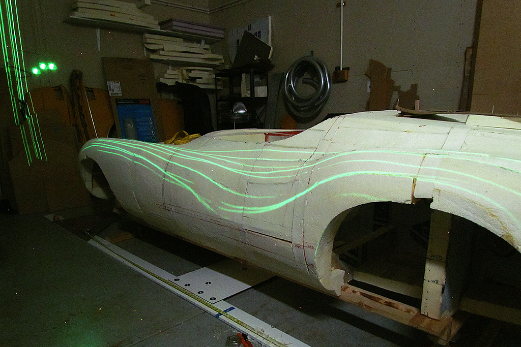
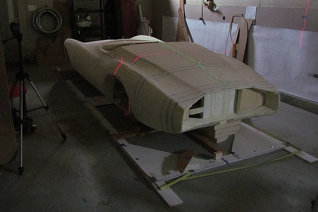
First, I tested an idea I had to use my red and my green lasers to establish a single point... hopefully in 3D space, even in the air!
I set them up at right angles to each other and turned on the vertical line.
I needed a vertical surface at the location of interest to be able to see both lines and bring them together.
On doing so, it quickly deflated THAT idea.
The more powerful green laser completely washed out the red laser.
And it certainly did not produce a point of light in the air!
"Dégueulasse! C'est domage."
Well... just how good is the rough shaping I have already done??
Let's use my new pattern to find out! (brave words, n'est-ce pas?)
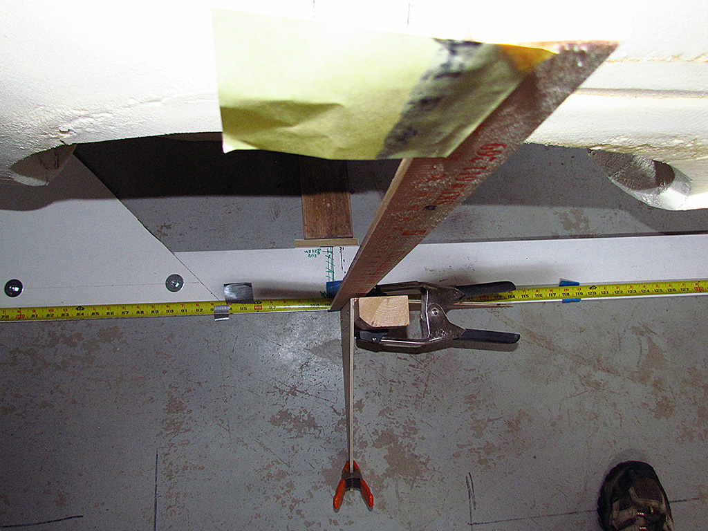
So I fit the template that defines the rear deck centerline front-to-back plus the rear deck front edge left-to-right onto the foam buck.
And sure enough (read: "Happily") it matches well with just a bit of light between it and the buck.
Well, it should! It was made from the same contours as the original foam sections I started with.
But it's good to check what should be so, "Non?"
"Mais, Si!"
"Très bien."
Getting serious, the first thing is to get everything level and measureable to be able to plot points on the foam buck to shape to.
The laser levels come out and so begins the process of raising/lowering multiple times until one side is level.
I start on the driver side - that is just my own preference.
BTW, my base line to level to is the line between the wheel centers, which is 3 inches below the centerline running from the nose to the rear wheel well.
One can see the crease on the door for that centerline just above the bottom door cut line.
Then I set up and do the same on the driver side.
Once set on that side, it is back to the driver side to check if it still is level and adjust it to make is so once again.
It did need a small adjustment.
Doublechecking the passenger side showed that it was still level there.
So on to the front.
I aligned the laser with the last marking on the driver side nose and checked if it matched the last marking on the passenger side nose.
Very happily, it did!
And then the same process on the tail.
And it, too, was good!
"Violà! C'est fini!!"
The next step to measure any point, anywhere, accurately is to create something like what was/is used in Detroit when working on full-size clay models.
That is, a measurement platform.
Now, I cannot afford to build a real platform and a bridge to do measurements.
Instead, I will create an outline of baseboards lying on the floor around the perimeter of the buck that will be marked off in inches and aligned to the front-back and rear wheel axle centerlines.
Instead of a bridge, I will use a pair of vertical measuring rods, yardsticks in actuality, to establish my left-to-right plane parallel to the wheel axle line.
Then I will set my laser level to the desired height after positioning the yardsticks along the measuring baseboards.
The laser crosslines will then give me my point to mark on the buck.
Simple - but tedious.
"Chouette! heh?"
Jan. 29: I took the afternoon to first establish the front-to-rear centerline using a laser and the two vertical positioning sticks.
The rear wheel centerline could be established using a large right angle laid along the laser centerline.
Another laser was cast so it just kissed the right angle at the same point left and right.
At the same time, this gave the location of the rear wheel centerline where it fell on the measure box.
It turned out that the box was correctly positioned for the driver-side rear wheel and the rear centerline.
I place a weight (my argon gas bottle) on the box at the rear driver's corner, checked the vertical positioning stick to match the nose center, and tapped the box with a hammer until the box aligned with the stick.
On the passenger side, the measure box inch marks did not - could not - line up with where the laser fell.
I just accept that the laser is correct and I will have to goback and remark the box to align the box to the car.
With the box aligned, I am ready to make measurments and mark out the ridge lines.
"En avant!"
FEBRUARY
It's time to transfer measuring points from my full-size drawings to the foam body.
I decide to start at the rear.
First I establish the front-to-rear centerline.
Next I begin casting the left-to-right section lines every three inches to match the grid on my drawings.
With my setup, I am unable to plot and carve to a point in 3D space in one step.
Instead, I can only plot a point in two axes at a time.
That means I will have to plot and carve to a point in two steps.
In my coordinate system, X is distance front to back, Y is height up and down, and Z is the distance left to right.
FEB. 4-9
In five sessions, I plot the location of the left and right rear hood and rear fender ridge lines by measuring from the front-rear centerline.
And I also plot the height of those points separately.
On Feb. 9, I begin to carve and shape the body once again.
I begin on the area between the hood and fender ridge lines on the passenger side, starting from the front to the rear.
It feels marvelous to begin seeing progress as the rasps shave off the foam.
FEB. 10-17
The new garage has heat! It is wonderful to flick a switch and not have to be distracted by chivering.
The approach is to first locate the rear fender and hood ridge lines from the front/rear centerline and then carve away foam to those lines.
Next I locate the height points above the wheel centerline for those ridge lines at each measured station point.
Then I carve away foam down to those height points, which obliterates usually the ridge line at those points.
So thirdly, I again mark the ridge line station points along those ridges and carve back in to them, which is usually enough to reastablish the ridge line, but this time, at the correct height.
Simple, just tedious.
But actually, it goes pretty quickly.
Using the laser and the fixed yardstick allows me to quickly mark the heights by simply raising or lowering the laser, which is set for projecting a horizontal line.
By the end of the weekend, I have a tight shape of the rear surface between the rear fender ridge lines all done.
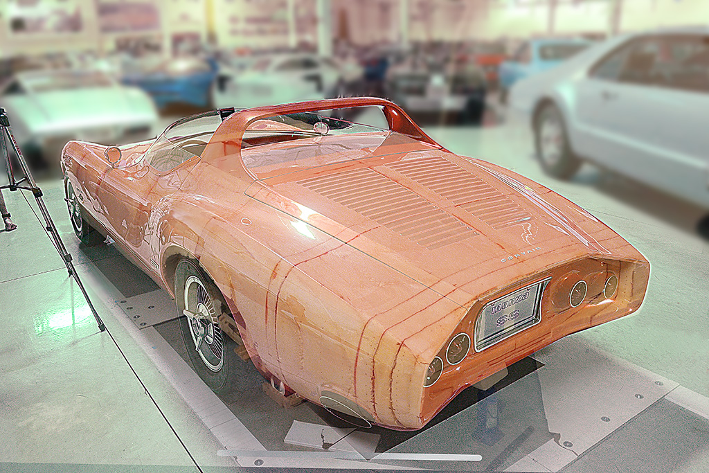
I then check my work by matching a camera station I did when I photographed the Monza SS in Detroit in 2016 and overlaying a photo of the foam body on top in Photoshop.
Happily, the outlines match very closely, so I did closely match the viewpoint.
Less evident is how well the curved surfaces are matching.
I will project a grid upon the foam body with a slide projector to see how those curves are looking.
MARCH
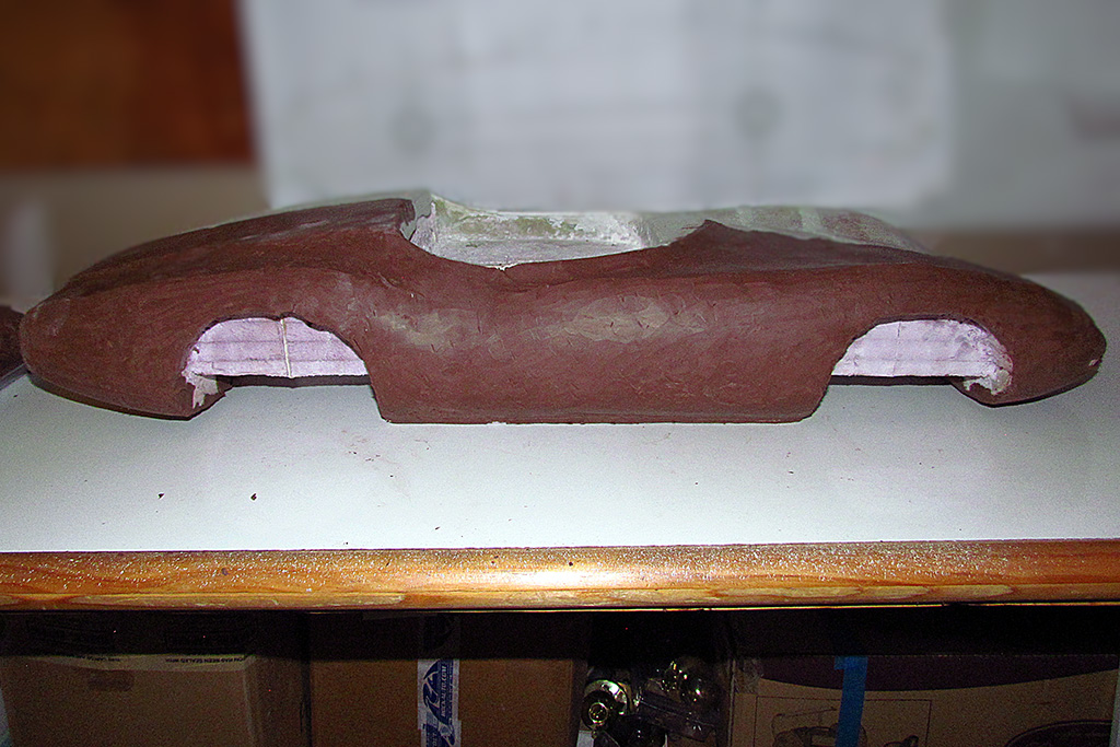
After nearly a month off because of life events, it is back at it.
During that time, I did get time to shape the rear fenders behind the rear wheels and below the fender ridge line.
I also defined the outline of the Kamm tail and smoothed out the recessed area inside the tail.
Finally, the week of March 12, I got two full afternoons and carved the front fender rigde lines and shaped the hood and fender sides, driver side one day and passenger side the next.
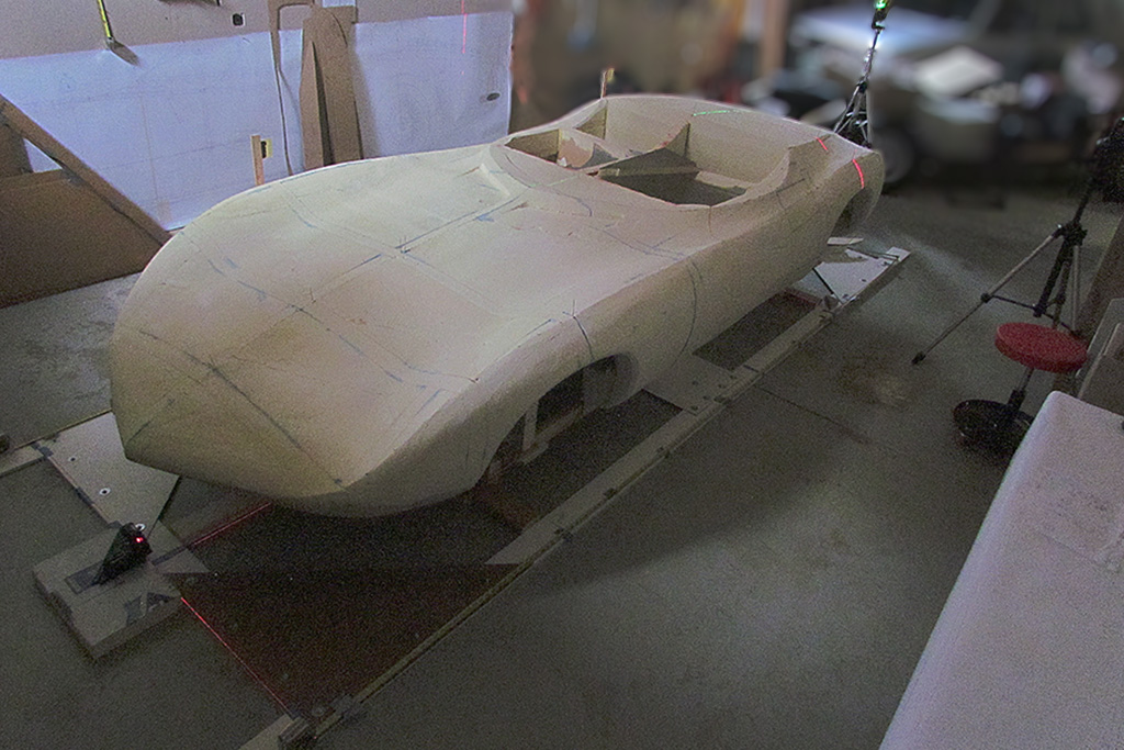
To my giddiness, I stood back and saw at last the car I have been making these last ten years!
The shape and body lines look very close to the original - good enough to be satisfied with!!!
The shaping of the large surfaces takes some upper body strength, but, really, is simple and easily done.
And to my pleasant surprise, it is a very tactile experience.
You can feel the surface and little by little work it so the rasp flows smoothly across the surface.
I was without thinking about it, able to make the left and right sides nearly symmetrical.
It went faster, and easier, than I expected.
Now to do the contour checks with more templates based on the contour lines.
APRIL
I shaped the driver side front hood and decided to do the front ventilation intake vents in front of the windshield.
That meant I needed to define the outline of the passenger compartment.
I tried plotting points as I had been doing, first on one side, then go over and do the other.
But the points were not coming out level!
I discovered I needed to be more careful setting up my vertical measuring stick.
Specifically, it had to stay in the same location at all times.
And I remeasured the points on my master drawing again, this time using the same measuring device, the one I use on the foam body, and measuring all points every 3 inches on the side view and plan view.
That eliminated 75% of the differences.
And THEN it hit me... just set up the laser level in front so the horizontal line shines of both sides for the same vertical height.
Simple. Done. Matching. Finished.
Next I shaped the passenger side front hood.
I checked it with the laser.
All looked good.
And for good measure, I checked the rear deck.
That was not good.
My slide projector test was giving me valid results.
The laser level "fer shur" confirmed the skewed lines.
I remeasured my rear points on my master drawings, and there was a slight difference of about 1/16".
I set up and replotted the ridge line points, and, yup, the driver side rear deck ridge should have been lower.
I rasped it down, shot the laser lines, and the difference was nearly all eliminated.
Door areas, wheel wells, and Kamm tail still to go!
But First. . . Let's learn a new technique!
WORKING WITH AUTOMOTIVE CLAY
The question is, how to give the foam buck its final surface.
Detroit has used a special clay to model their designs full-size.
But the technique I have been planning to use does the final surface in fiberglass and Bondo, a technique that Mel Francis does VERY well.
So I finally bought 10 lbs of the special clay made by Chavant and some sculpting tools.
It has a high, wax content that allows it to be heated and applied, yet still workable at room temperature, and hard enough to hold its shape and be smoothed.
The clay came in 1-3/4 lb sticks. I first had to learn how much to heat it.
I used a small tabletop oven/air fryer. The fan is a good feature.
I used a meat thermometer to get a better reading. It needs about 45 to 60 minutes on low-ish heat.
It can be applied at 140 deg, but cools very quickly.
It is best to get it to 170 degrees. The clay better adheres to the foam at that temp.
At 180 to 185 it literally starts to melt and puddle.
And it is too hot to handle. 170 deg. was almost too hot, even wearing nitrile gloves.
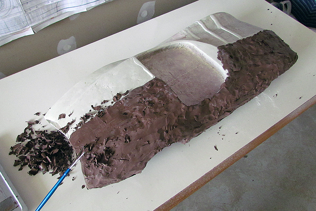
Slab it onto the foam and work it around into an even layer.
For my test, I am applying clay to half of my 1/5 scale model.
I apply up to 1/4 inch layer of clay. It took two sticks, or 3-1/2 lbs to cover.
I am hoping to carve it down to 1/8 inch or less.
Once cool, it is hard to work.
It required more muscle than I expected, but as I practiced sculpting with the tools, it was less so.
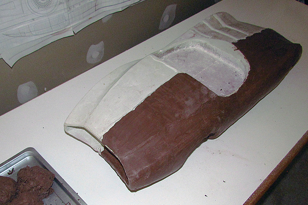
I roughed out the clay just by eye. It took 2-1/2 hours to do so.
I scraped off at least 1 lb of clay.
If the clay is clean, it can be reheated and used again!
That's one of the advantages of this clay.
Conclusions so far are mixed.
I am concerned about the weight of the clay, and also the amount of effort to apply it and sculpt it off.
My foam buck does not have the wooden frame to support the weight of the clay, and I am not convinced I can retrofit one under the buck.
I also begin trimming out the wheel wells.
I cut a new outline template and trace it onto the foam.
I must keep in mind the extra 1/2 inch of chamfer all around each wheel well.
I will try to keep enough material to carve the chamfer, but that will not be possible for every well.
And then my contract workload swamped me. Back in a week or so.
MAY
Back at it again, two weeks later.
I continue working on the wheel wells.
Checking my work with my template, I discover the cutoutline was too large.
I need to fill in at the front of the front wheel well, PLUS, add a half inch for the chamfer.
I decide to glue large foam chunks onto the entire wheel well cutoutline and start the cutout again.
The rear wells, being done after the front, came out better, and even had enough material to do the chamfer.
I calculated that the chamfer angle was 40 degrees from the vertical, but that is so close to 45 that I use 45 as my angle.
If I don't like it, I can fix it with Bondo.
June
Well . . . Most of May and all of June was taking a step back and rethinking what I've done. It is close, but how will I proceed?
A couple of people who have been encouraging me and giving me advice asked a list of questions, based on their very rich experiences in building cars.
All were very good questions that are needing pretty good answers.
And in working thru them, I am reviewing what I have done and how I got here and the decisions I made, and reevaluating what I am doing and going to do.
And doubting myself on how I have problem-solved some critical things.
There are, of course, the practical questions about how to make the molds, or if I even need to make one!
But as I approach the hard-surfacing (as opposed to the soft-surfacing I am doing with foam), I am running into inconsistencies in my measurements.
The problem particularly arose when checking what I have already done on the Kamm tail cove.
It's wider on the left than the right - okay, it's only by 1/2" or so, but it is also too high a lower cove rim.
To make changes requires glueing in foam pieces.
The glue seams cause problems when I sand at too close an angle to the glue surface.
Yah, I can make an entirely new tail and cut off the old and glue on the new.
But the bigger question is, 'do I have good dimensions???'
I don't know!
So I decided to go back to my 3D Photomoderler file and finish it off as I original intended - with contour lines AND surfaces.
And THAT is what I have been doing all June!
I have added and fine-tune-adjusted hundreds of surface points.
And I began to finally turn the points and lines into surfaces in the last week of June.
It is hugely tedious and slow, but the accuracy is improving, and showing to my eye.
I am learning how to do points and lines to be able to make surfaces, such that the file differs from the earlier version.
Photomodeler itself is quite powerful, but is not a full-blown, regular 3D program like Blender or the pay-for apps.
It is geared to digitize photos into 3D models, particularly recreating physical spaces.
I think I am pushing its boundaries just creating a surfaced model of an organicly shaped object such as a 1960s car.
And it is taking a lot of time.
Very likely, I will need to set it aside and begin the hard-surfacing while it is summer and I can open the garage to get ventilation.
I need the surfaced model to get my finalized contours AND . . . to make 3D models in various scales.
So close . . . and so much to do . . . and so time-constrained to do it.
July
Well, That plan did not pan out. Mainly, I could not settle on a final set of plans for the Kamm cove.
Again, it was a matter of balancing my PM-calculated dimensions against published ones of those I made in 2016. I kept tweaking the lines.
Twice I thought I was satisfied with what I came up with, until I applied them against what I had on the full-sized foam body.
The first round that started in May was continually revised since then to create an accurate, or at least, a definitive 3-view drawing of the Kamm cove and its contours.
I used photos I took in 2016 and 2019 to check outline shapes and feature positions, especially for the taillights.
After a couple of test tries on the foam body, I was confident I had a good set of lines by the end of September.
September - December
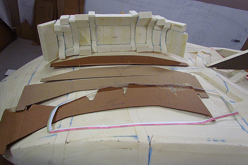
The next step was to create an accurate perimeter of the Kamm cove outline in actual dimensional lengths.
The process is tedious. It needs to be done in smaller segments and adding those segments incrementally to each other.
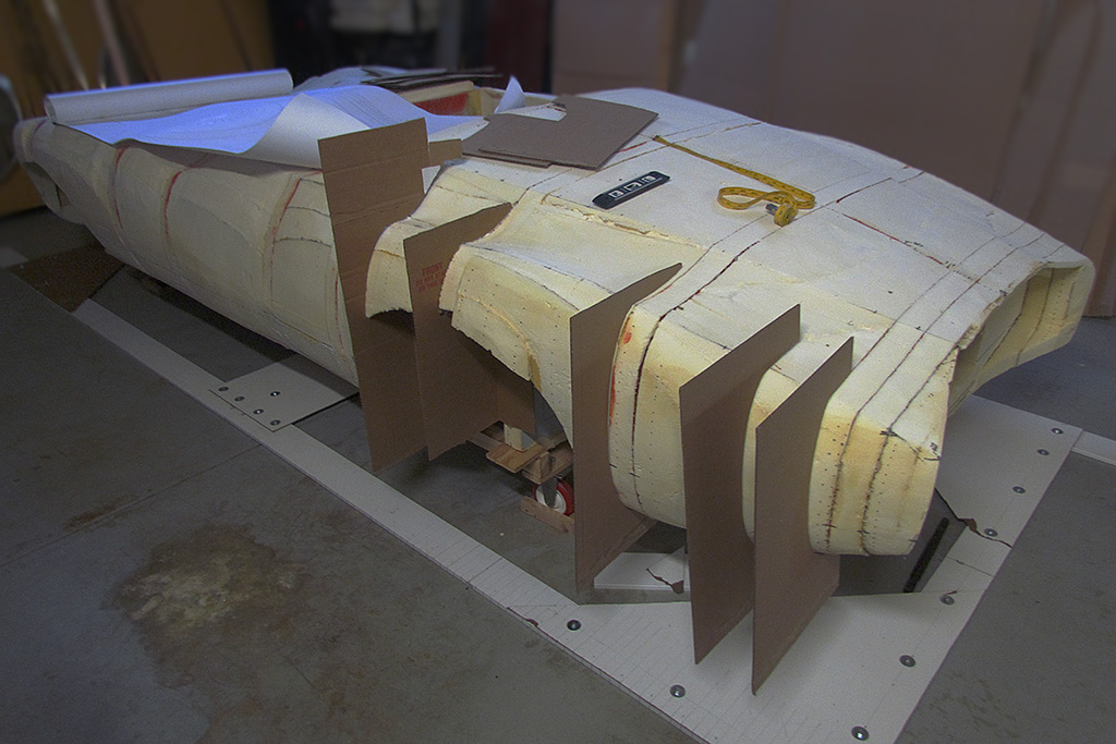
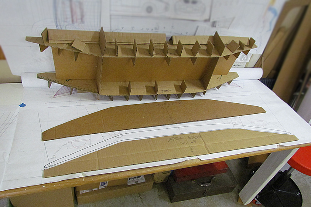
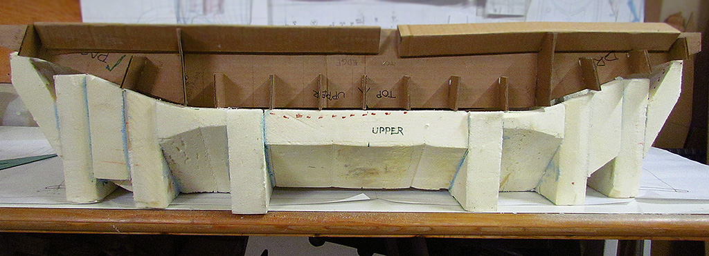
What is also needed is a frame to mount the perimeter segments to, so a frame based on the actual widths and lengths and heights to selected points along the perimeter was made of cardboard.
It looked like a large, distorted shipping carton insert. That was completed in early November. The perimeter segments as a full outline was completed in early December.
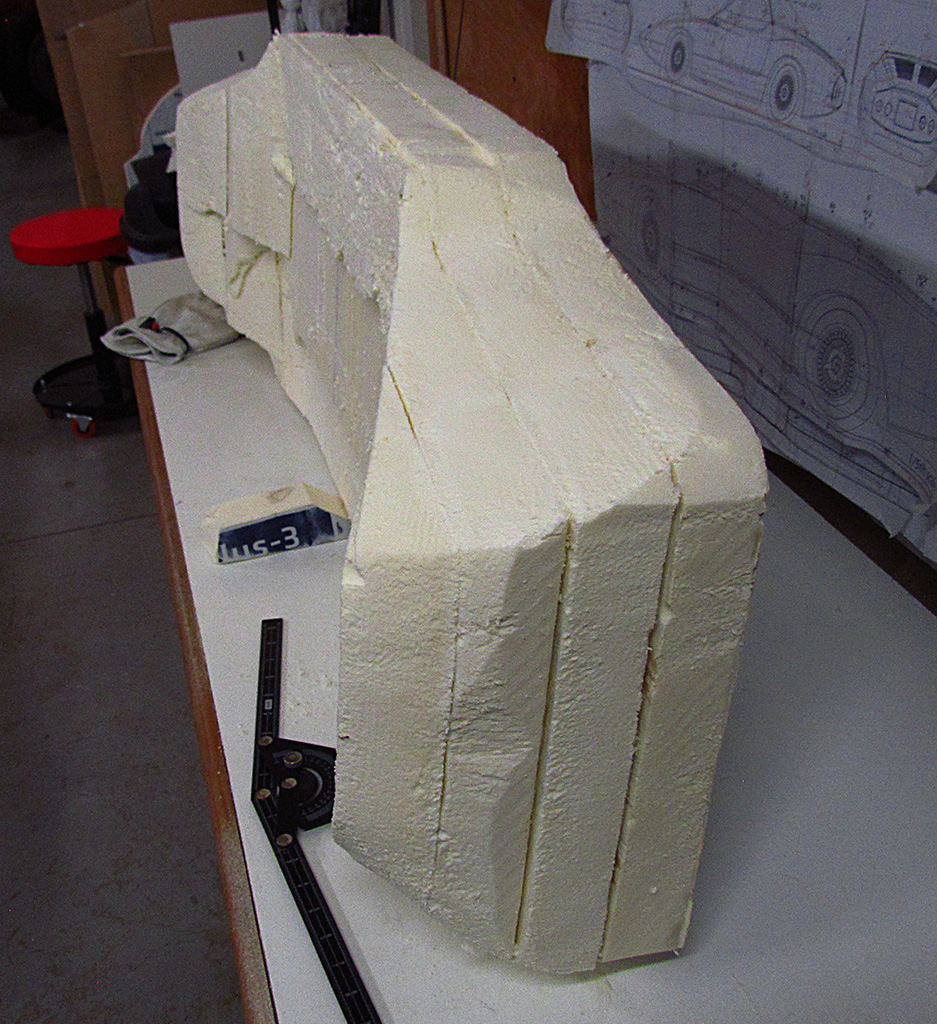
Back in September, after my first attempt had failed to make a foam block to carve the Kamm cove out of, I made another attempt with a different approach.
This time, I cut out cross-sections out of foam and filled the space between them with foam blocks.
Then the whole assemblage was trimmed to the rear view outline, and then the upper and lower edges, as seen looking down, were trimmed.
And finally, the outsde vertical edges were trimmmed to shape as seen from the side view.
This defined the exterior edges. Now the concave surface of the cove could be carved . . . with the help of more contour templates, which now must be made.
SIDEBAR: Glues
To assemble the foam panels, I have to glue them together. I cannot say I have found the best solution.
Initially, I began by leaving the foil coating on the foam and applying contact cement to that.
It worked great! But, it turned out to be a poor solution.
The problem came when I was rasping the foam down to shape.
Whenever I hit a seam between two panels, I ran into a double thickness of foil with rubbery cement inbetween.
And that seam did not rasp as easily as the foam, and so it left a raised edge.
I eventually dug those seams out, but it left behind a crevase that needed to be filled.
So much for idea #1.
I next used the epoxy-like Gorilla glue.
It was thick like honey (and looked like it, too!), and had to be spread out, but not too thin.
It needed to be in contact with both foam surfaces.
I used a misting spray of water to help it harden.
It would hold and could be rasped more easily than contact cement.
If applied thick enough, I did not need fill a seam.
But, OH!, was it drippy and sticky.
I ruined every pair of pants I did gluing in with obvious hardened drips on 'em.
But the problem here was that it did not hold as strongly.
It could be pulled apart.
The surface of the foam granulates into fine duct.
The glue adheres well enough, but the foam surface disintergrates and departs the hardened glue.
So I started using the commercial grade of white glue, purchased at Home Depot.
It spread easily, and cleaned up well if it dripped.
It did not hold as well as Gorilla glue, but it was easy to rasp, doing little harm to the foam.
The big problem here was the foam surfaces had to fit tightly with no gaps or else the glue would not dry or would drain away.
Even so, sometimes, because glued surfaces could not get any air on them, the glue just would not dry - even after a week!
There HAD to be a better way.
Then I found foam glue at Home Depot.
It came in a cartridge, like liquid nail.
It was light blue, and thicker than paste, very like liquid nail or silicone caulk.
It would spread, but did have to be thick enough to be in contact with both surfaces.
It dried within a day, but it really could not be rasped down.
Instead, it had the consistency of rubber, and would have to be pulled out of a seam if it protruded above the foam surface.
So at this point, I use the white glue or the foam glue.
Neither are ideal. It just depends on how easily I want to work the surface, or how strongly I need it to hold together.
And that is where it is at year's end.
Check out 2024 for more progress!
"Très bien."
SIDEBAR: Glues
To assemble the foam panels, I have to glue them together. I cannot say I have found the best solution.Initially, I began by leaving the foil coating on the foam and applying contact cement to that. It worked great! But, it turned out to be a poor solution.
The problem came when I was rasping the foam down to shape. Whenever I hit a seam between two panels, I ran into a double thickness of foil with rubbery cement inbetween. And that seam did not rasp as easily as the foam, and so it left a raised edge. I eventually dug those seams out, but it left behind a crevase that needed to be filled.
So much for idea #1.
I next used the epoxy-like Gorilla glue. It was thick like honey (and looked like it, too!), and had to be spread out, but not too thin. It needed to be in contact with both foam surfaces. I used a misting spray of water to help it harden. It would hold and could be rasped more easily than contact cement. If applied thick enough, I did not need fill a seam. But, OH!, was it drippy and sticky. I ruined every pair of pants I did gluing in with obvious hardened drips on 'em.
But the problem here was that it did not hold as strongly. It could be pulled apart. The surface of the foam granulates into fine duct. The glue adheres well enough, but the foam surface disintergrates and departs the hardened glue.
So I started using the commercial grade of white glue, purchased at Home Depot. It spread easily, and cleaned up well if it dripped. It did not hold as well as Gorilla glue, but it was easy to rasp, doing little harm to the foam.
The big problem here was the foam surfaces had to fit tightly with no gaps or else the glue would not dry or would drain away. Even so, sometimes, because glued surfaces could not get any air on them, the glue just would not dry - even after a week!
There HAD to be a better way. Then I found foam glue at Home Depot. It came in a cartridge, like liquid nail. It was light blue, and thicker than paste, very like liquid nail or silicone caulk. It would spread, but did have to be thick enough to be in contact with both surfaces. It dried within a day, but it really could not be rasped down. Instead, it had the consistency of rubber, and would have to be pulled out of a seam if it protruded above the foam surface.
So at this point, I use the white glue or the foam glue. Neither are ideal. It just depends on how easily I want to work the surface, or how strongly I need it to hold together.
The Build--2023
January

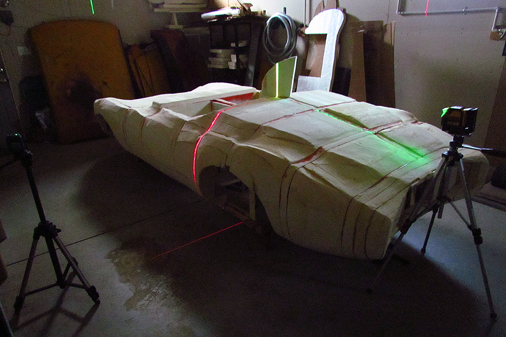


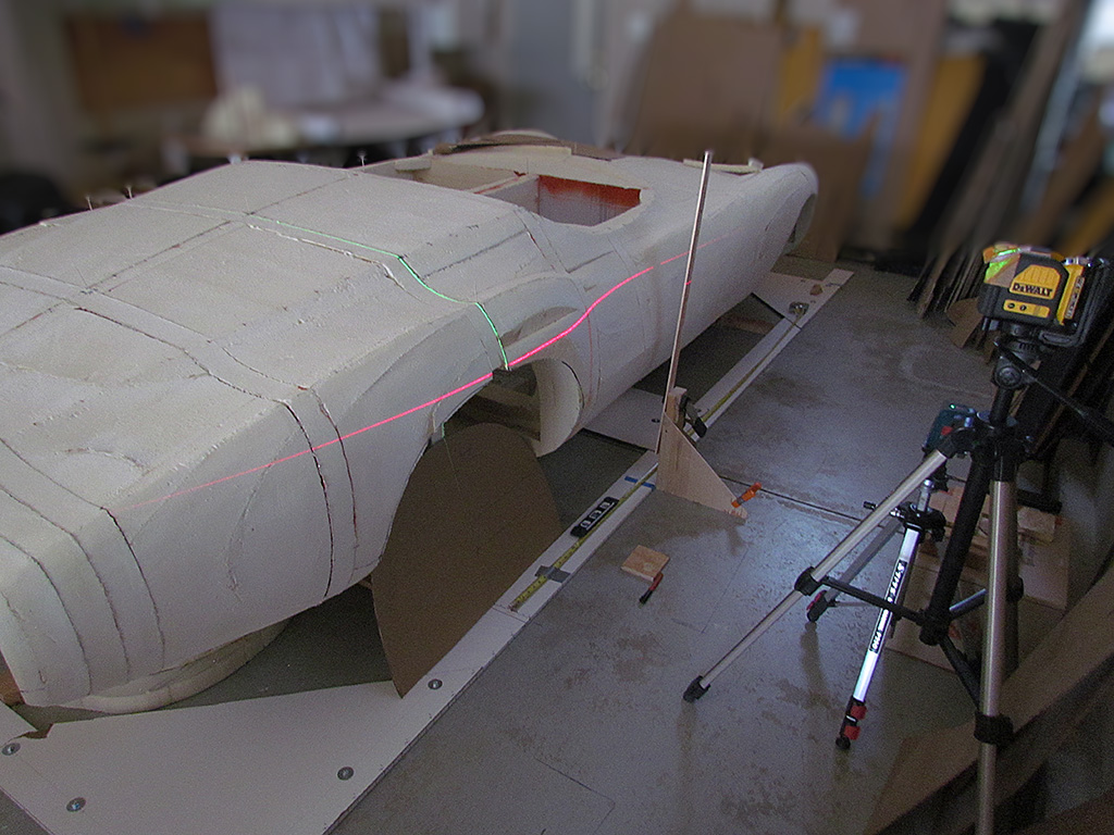
1st ROW - Leveling the Foam Body
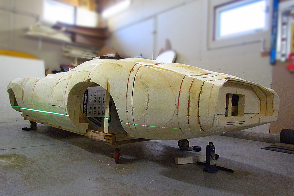
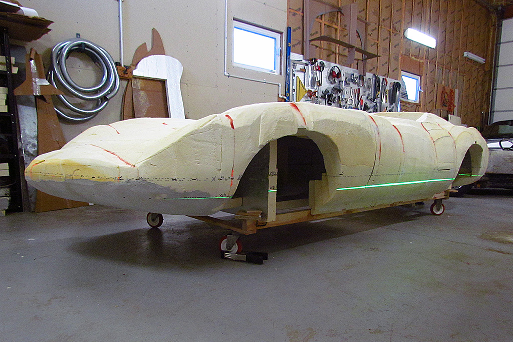
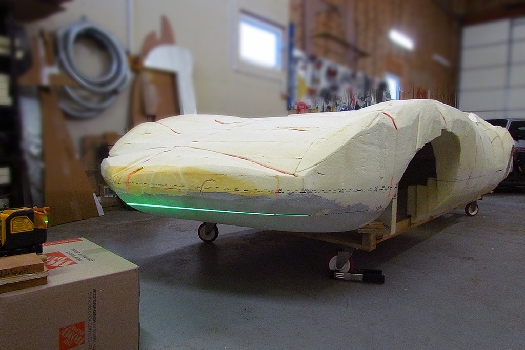
(L) The new garage floor is good, but no floor is absolutely level.
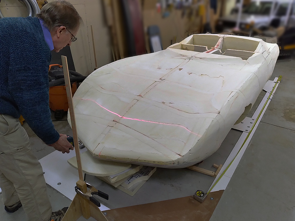
(CL) I used my laser levels to make the foam body level all around.
(CR) First the driver side, using the wheels centerline as my datum line horizontally.
(R) Then the passenger side, then the front and rear. It all lined up quickly compared to other bouts of leveling.
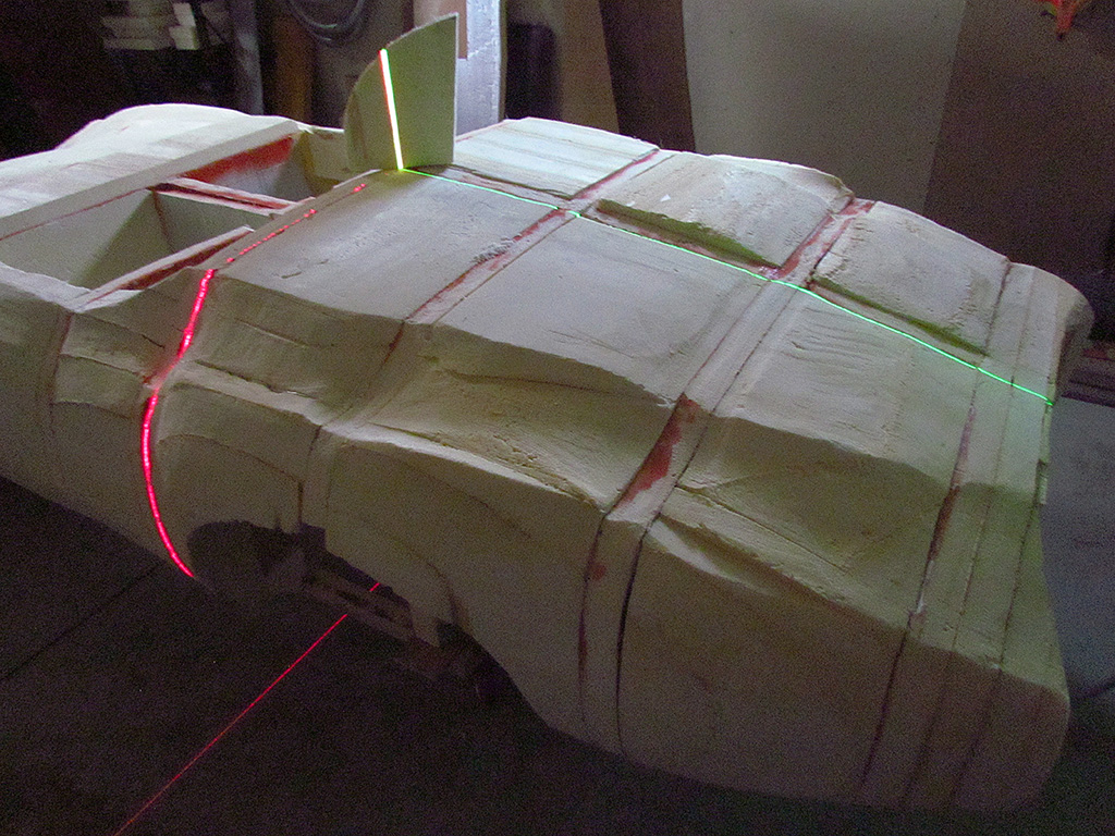
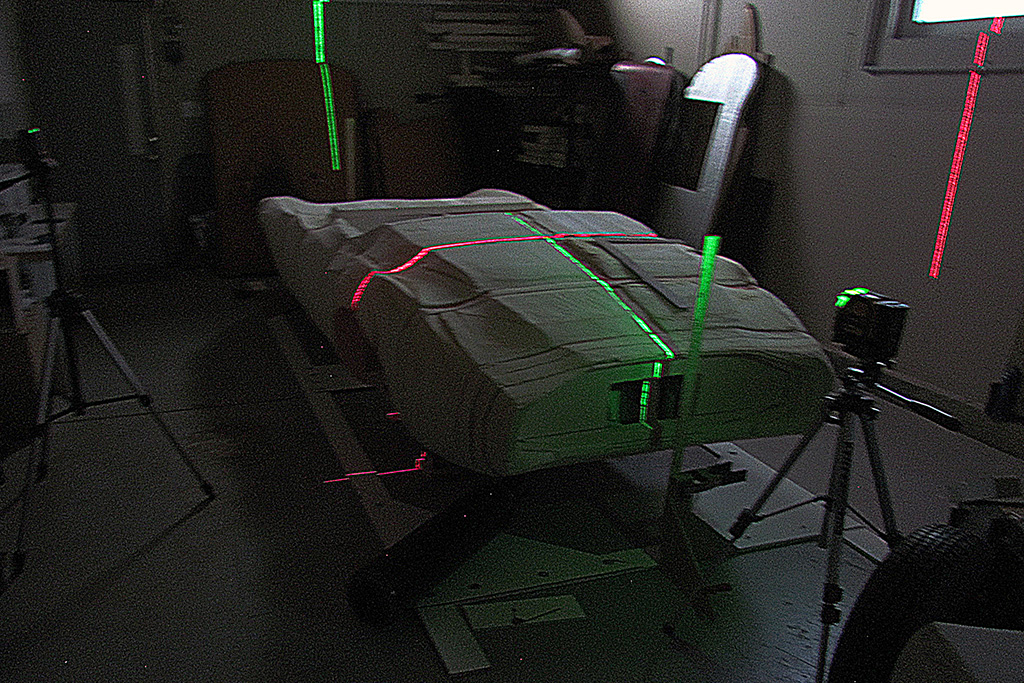
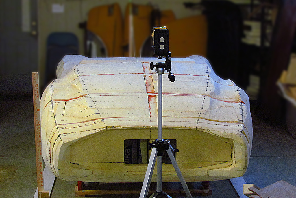
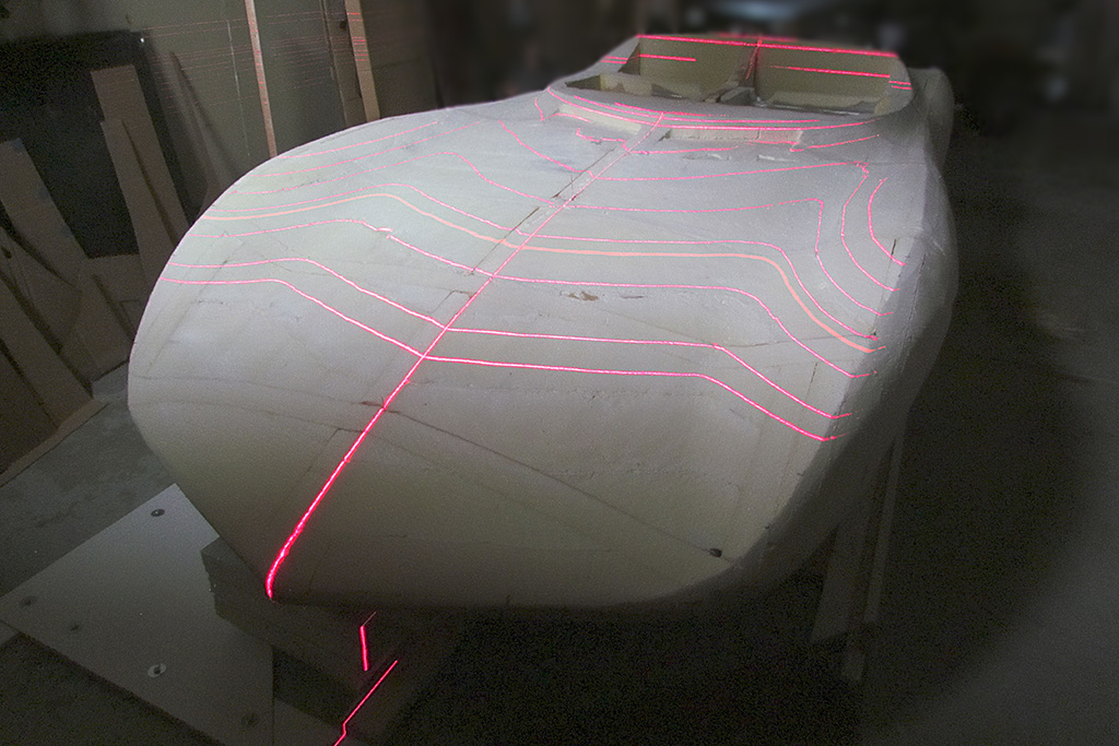
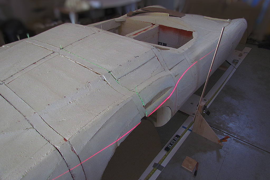
2nd ROW - Cross-Laser Intersection Test, and Pattern Matching
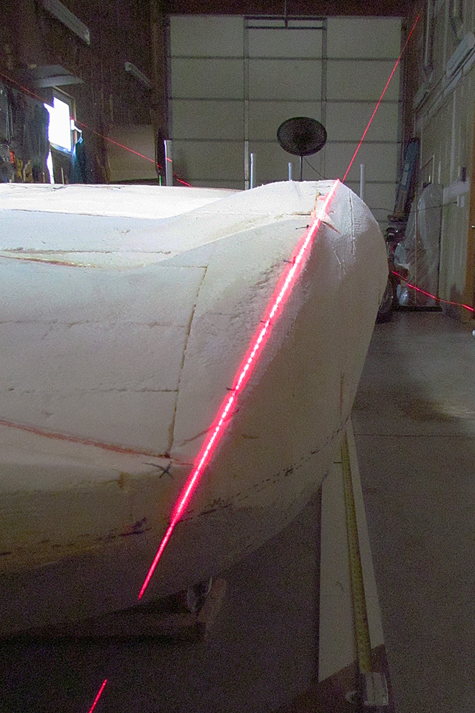
(L) Then to test an idea I had. What would happen when the red and the green lasers intersected? Could I use them to establish a single point?
(CL) The answer was quickly determined to be 'No.' The green laser is more powerful and washes out the red laser.
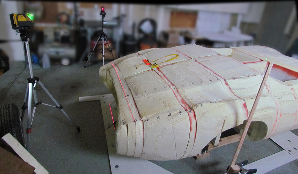
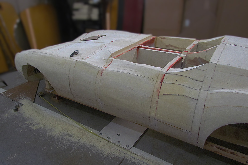
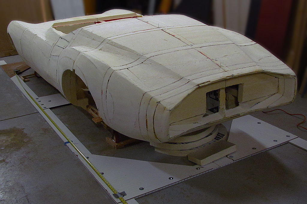
(CR) Finally, I used one of my patterns to check how close my curves were. This one goes along the rear deck centerline lengthwise and the curve at the front of the rear deck, behind the seats widthwise.
(R) While not perfect (some light shows between the pattern and the body), it IS pretty close and good. Bondo should take care of the irregularities.
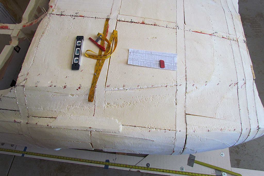
3rd ROW - Checking the lines and curves
(L) The measuring box pieces laid out. Note the triangular corner pieces to hold it together at right angles.
(CL) View from other direction.
4th ROW - Leveling and Establishing XYZ Axes
(L) The measuring box is aligned to the centerline front-to-back with a laser and the two vertical position sticks. Then the rear wheel centerline is established by laying a right angle along the laser line and casting a 2nd laser along the perpendicular arm of the right angle. That is extended left and right and the vertical laser line point down to the location of the rear wheel centerline on the measure box.
(CL) The location of the rear wheel centerline is confirmed and drawn left and right using the laser as the guide.
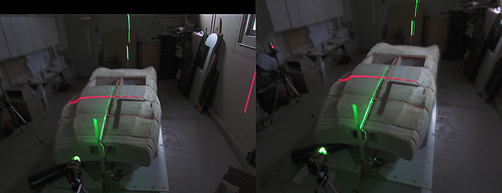
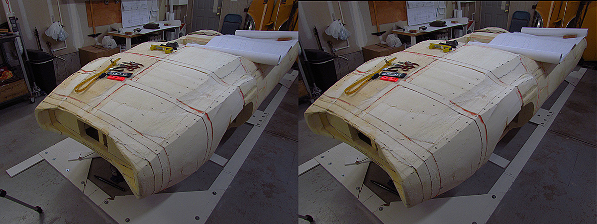
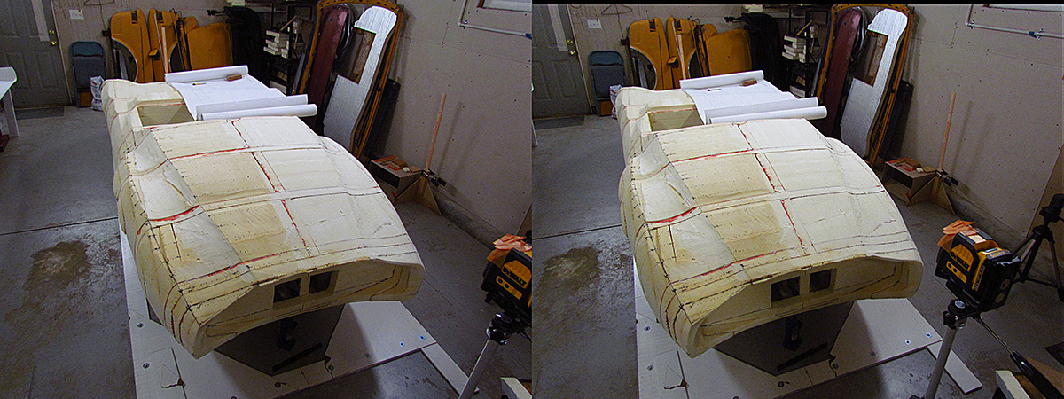
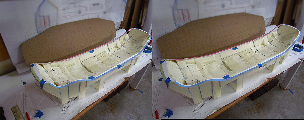
(CR) A stereo view (parallel viewing method) showing the two centerlines after establishing the alignment.
(R) A stereo view (parallel viewing method) of the rear wheel centerline laser on the driver's side.
February


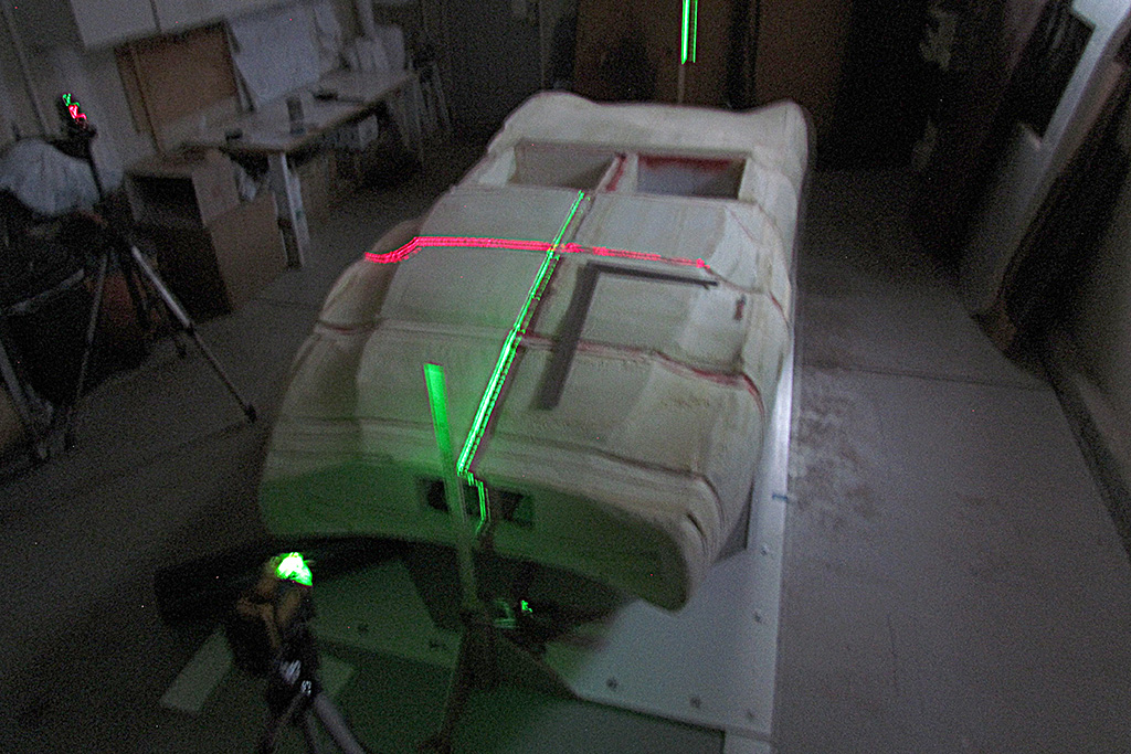
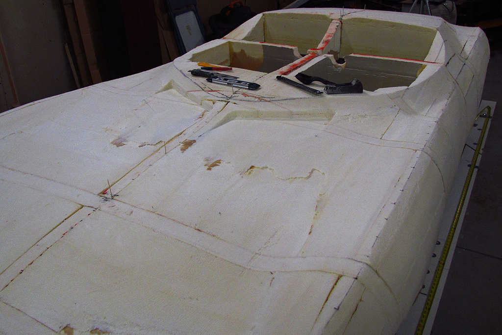
1st ROW - Plotting Points
(L) Checking, checking, checking. Both lasers are on and at right angles to each to see that there is alignment
(CL) A look-down view of the same. The ridge line station points are marked.
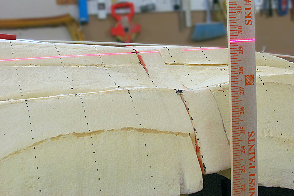
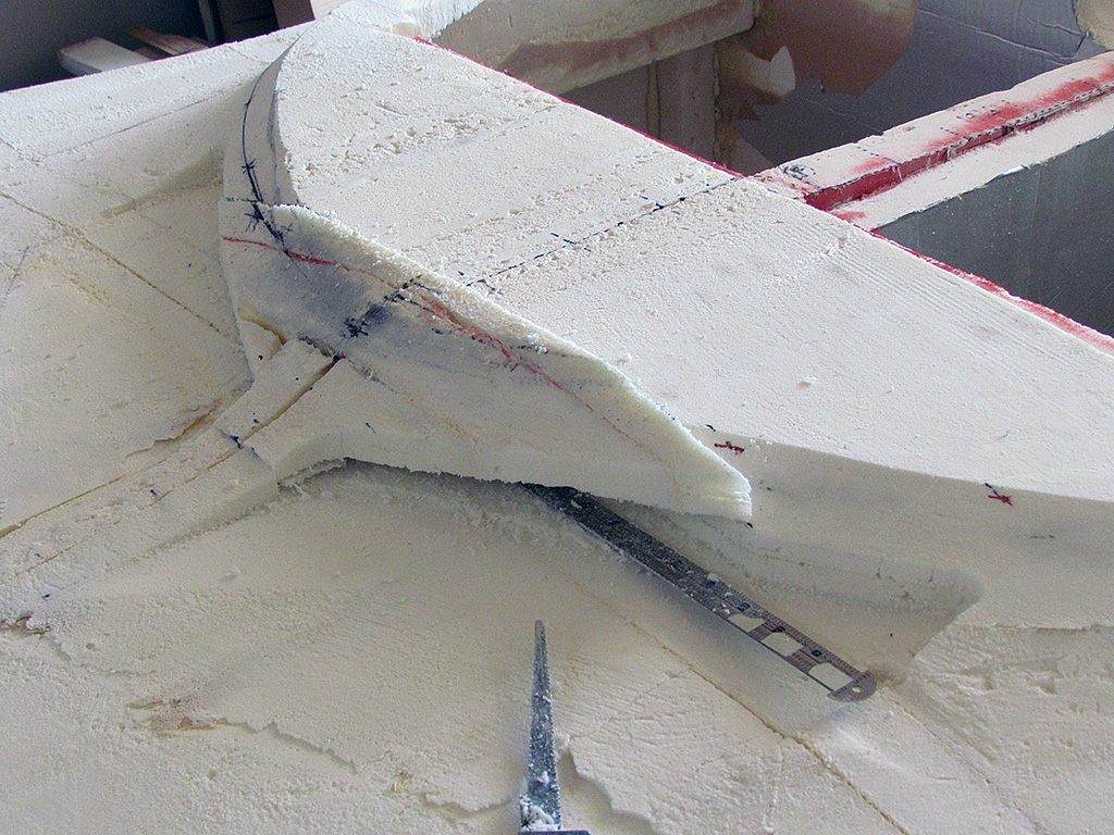
(CR) And a close-up of the laser used to mark the height station point. It typically falls below the already-marked station point established from the centerline.
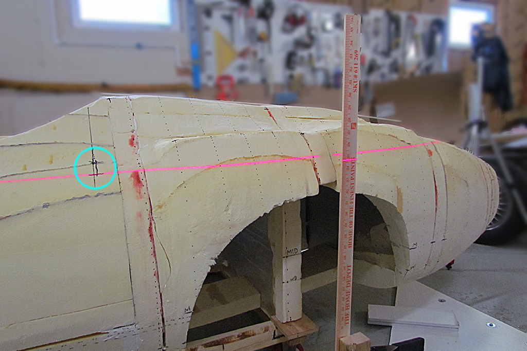
(R) Here is a good example. Note the cyam circle. The magenta line marks the correct height but the cross mark in black above that line marks the location relative to the front/rear centerline. I will have to carve into the foam to that point and remark the location from the centerline.
2nd ROW - Carving Foam
(L) This shows the overall differences. Cyan are the points from the front/rear centerline. Green are the heights for those points.
(CL) Here I have connected the ridge lines using a flexible curve. From this viewpoint, I can see how smooth they flow.
(CR) Now I have done the first step on the passenger side hood ridge line by carving to the station points marked from the centerline.
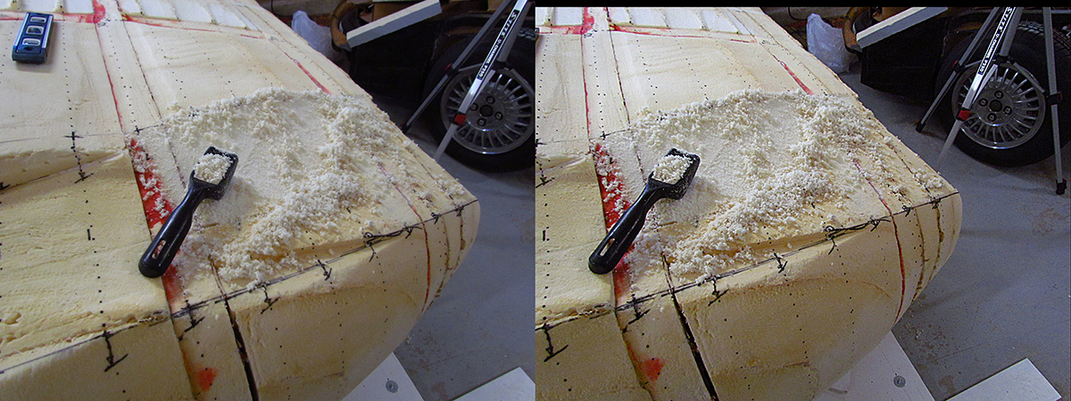
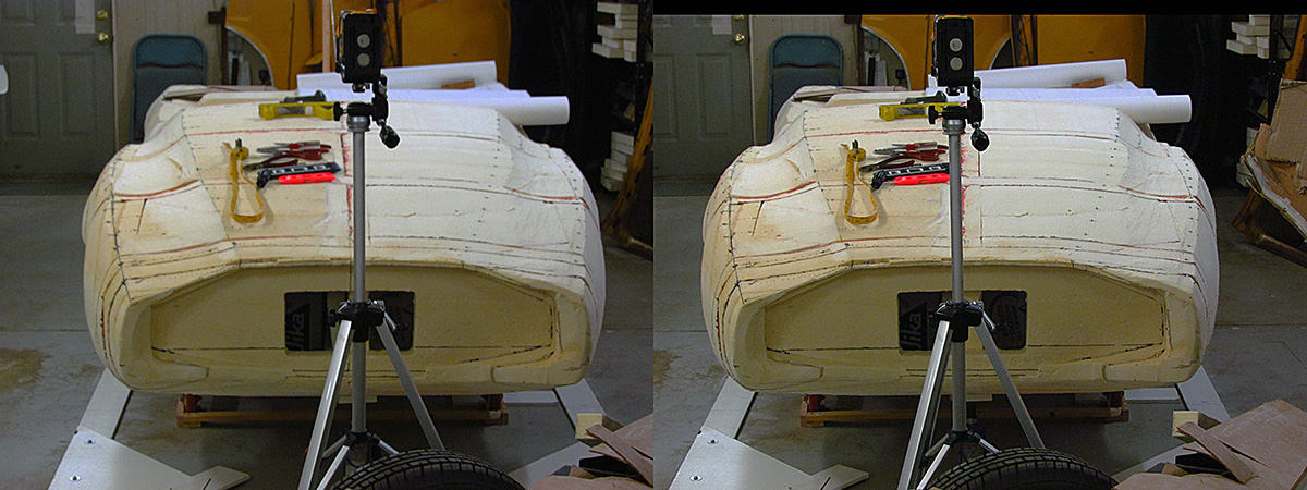
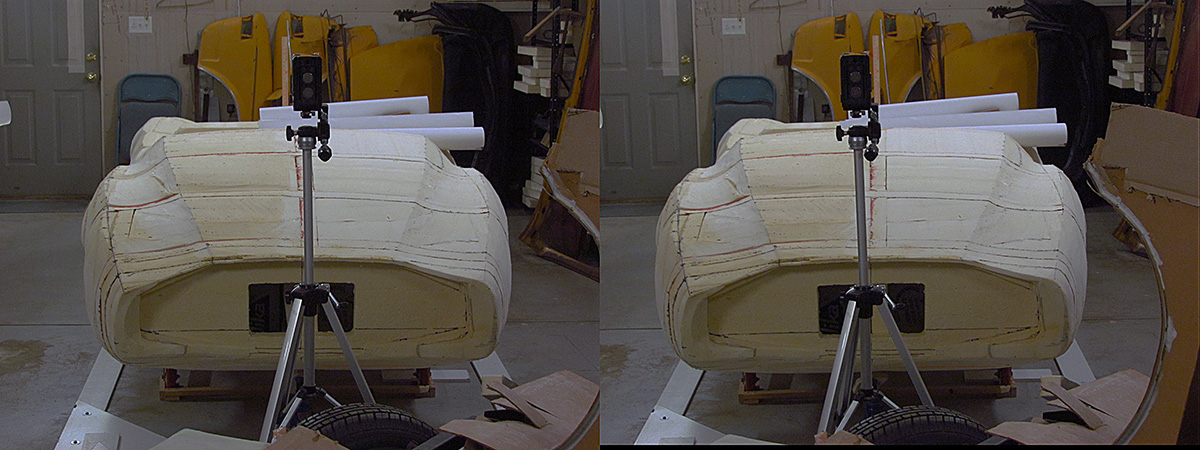
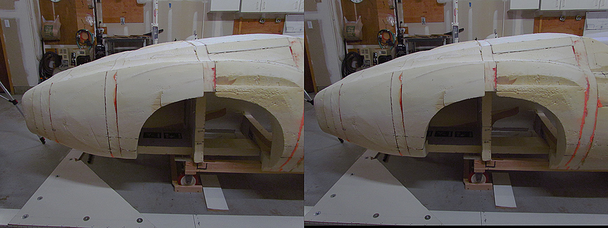
3rdst ROW - Final Shaping, Passenger Side: Stereo Views, Parallel Viewing Method, As Used With Stereopticons
(L) I use this rasp to do smaller area shaping, and a shopvac to clean up before it all scatters.
(CL) Taken down to the ridge line marks on the first section behind the seats
(CR) Taking it down to the height marks.
(R) Re-plotting the marks from the centerline.
4th ROW
(L) Re-plotted marks as seen from about 20 feet back.
(CL) The same view, but now the passenger-side ridge lines have been established in x,y,z space and the surface smoothed out.
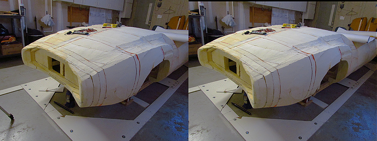
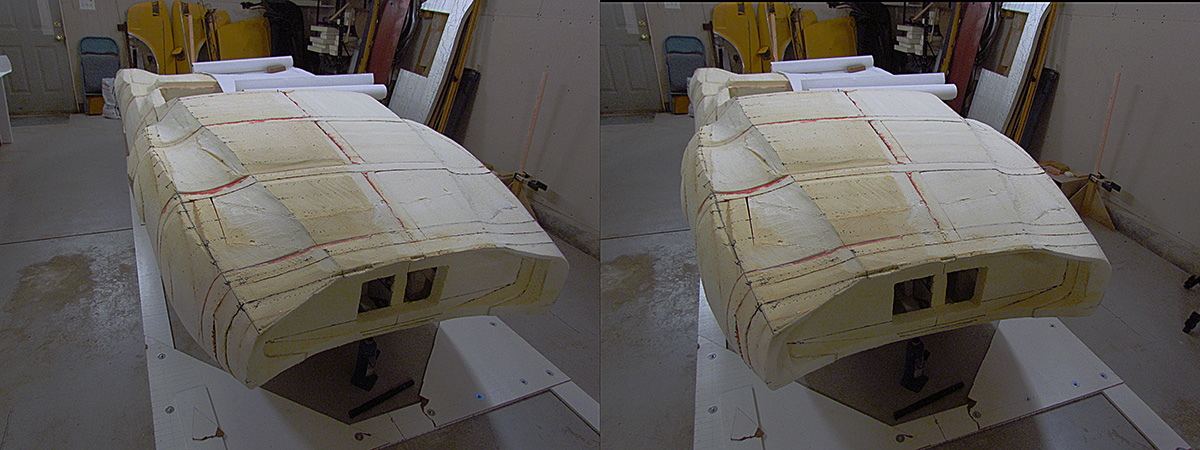
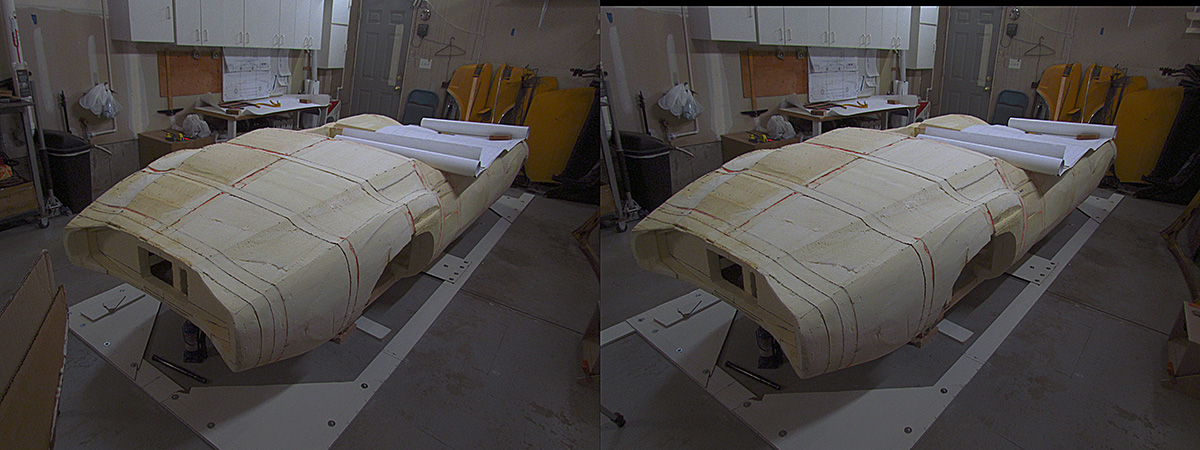
(CR) The passenger side has been replotted and shaped to the correct ridge lines. This and the next four compare driver side (before) to passenger side (after).
(R) Same state, different camera position.
5th ROW
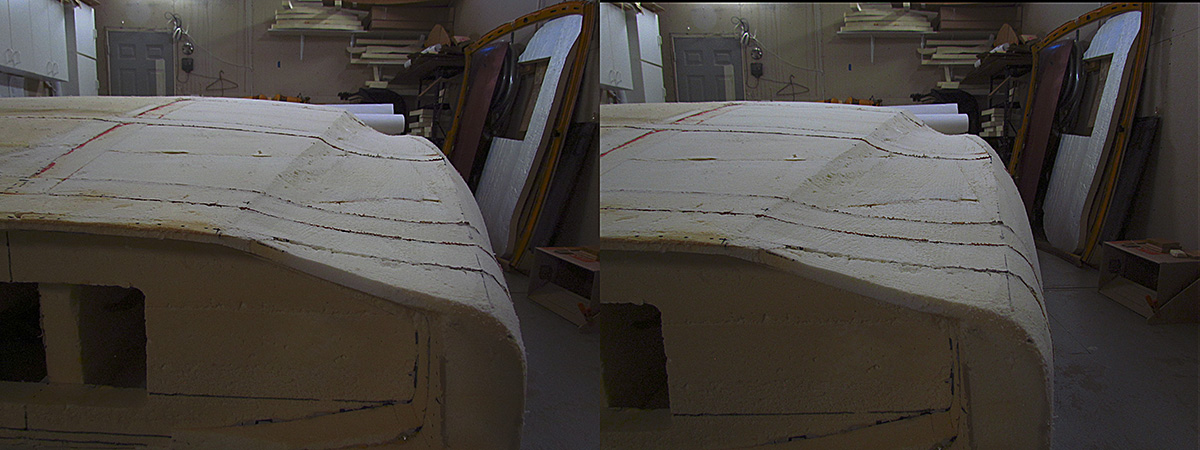
(L) Same state, different camera position.
(CL) Same state, different camera position.
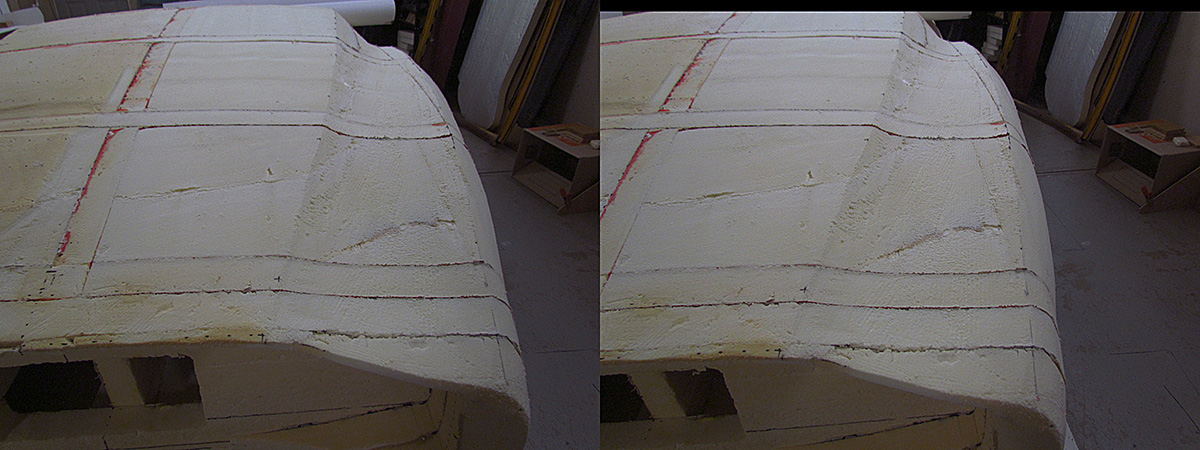
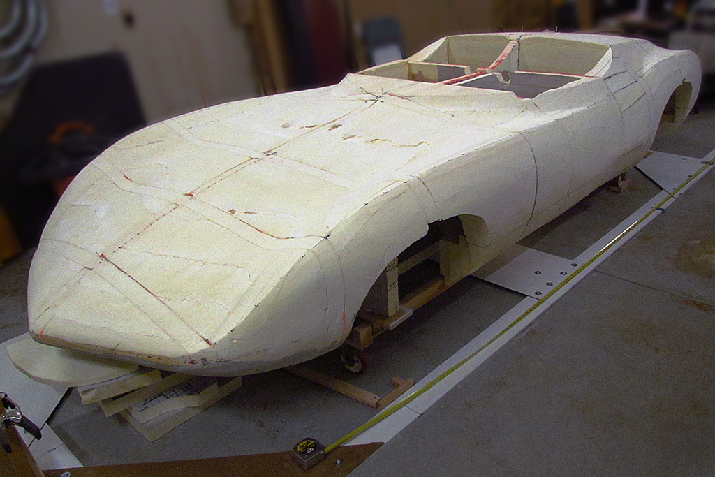
(CR) Looking forward along the finalized passenger side.
(R) The same. I am trying to see how smooth the curvatures are.
6th ROW
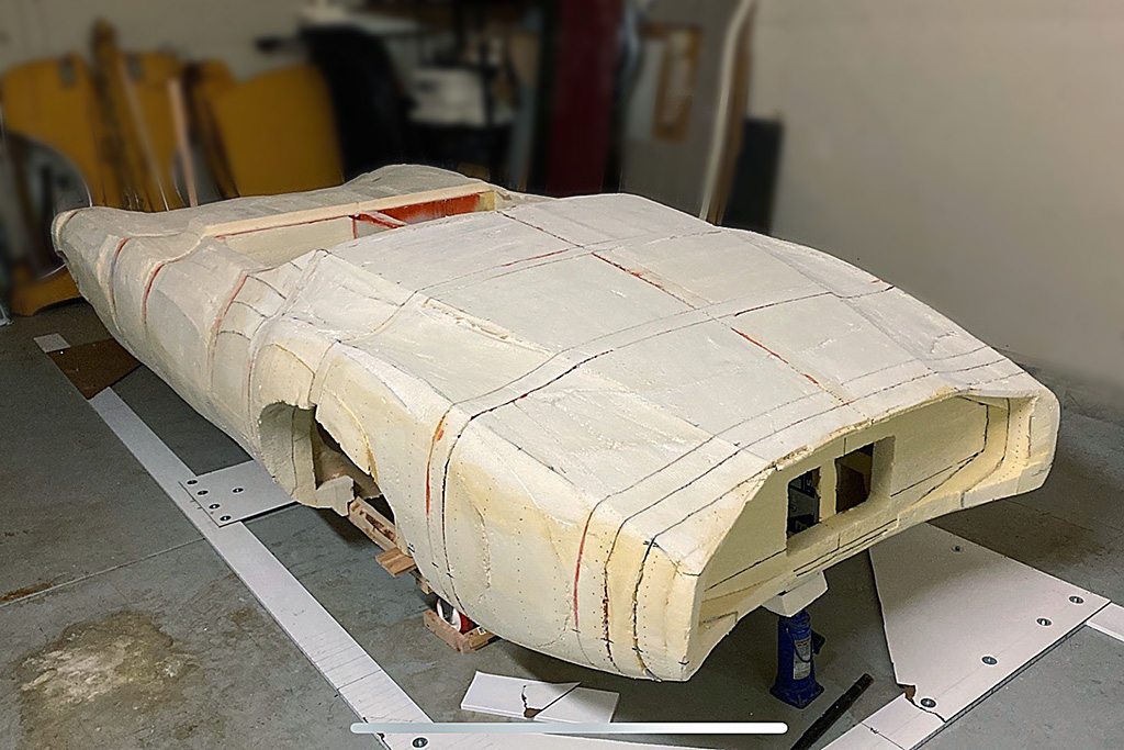
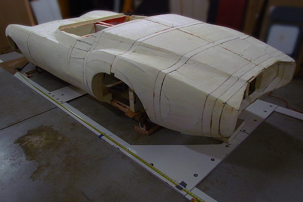
(L) The passenger side in side view. The fender below the rear fender ridge line is not finalized.
(CL) Looking back along the section defined by the finalized passenger rear ridge lines. I will need to evaluate this against photos of the actual car.
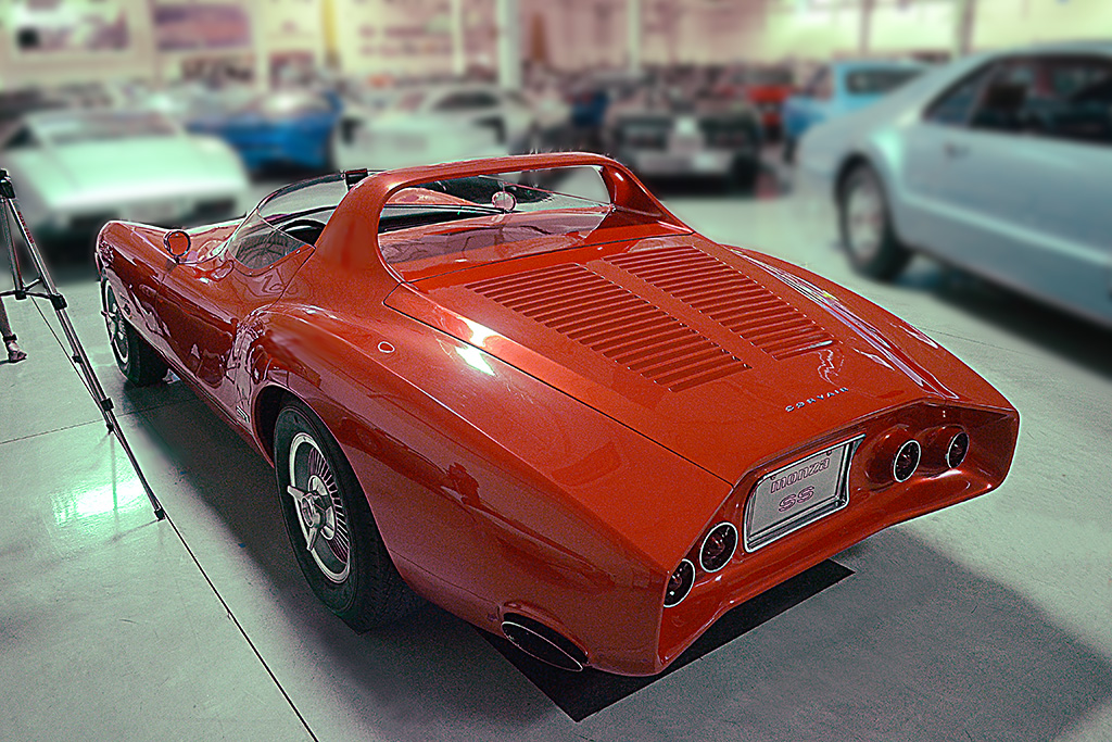
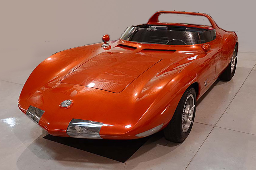
7th ROW - Comparing to the Original
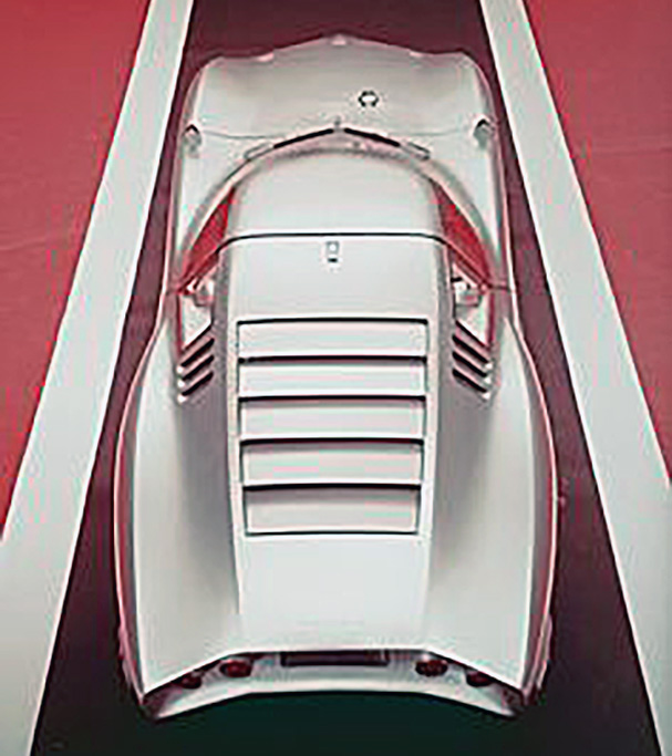
(L) Here is the view of the actual car from my visit in 2016.
(CL) Here I have matched the camera position looking at the foam body. The viewpoint is very close and the body ridge lines align very well. This is good progress!
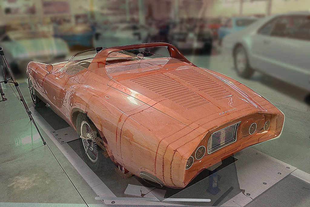
8th ROW
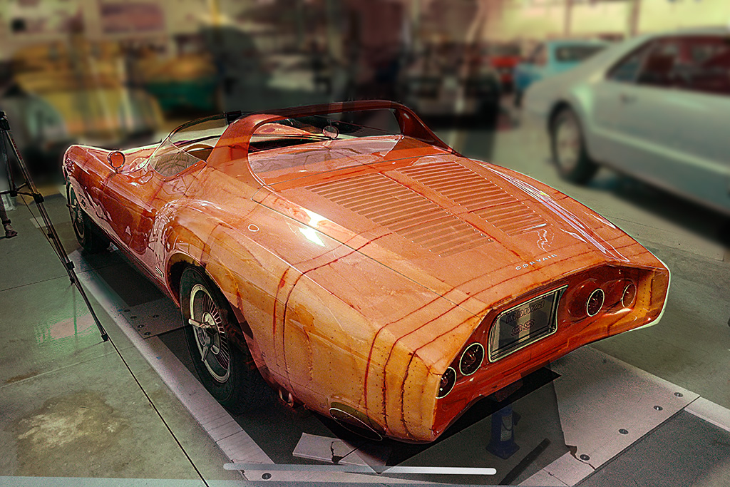
(L) In Photoshop, I overlaid the two images and tried different filters. This one is a simple overlay with the foam body set to 70% transparency.
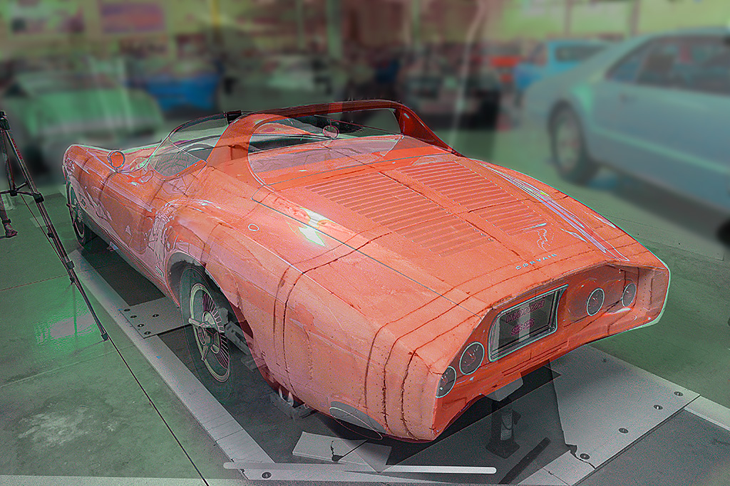
(CL) Here the filter is changed to "screen"
(CR) Here the filter is changed to "hardlight"
(R) Here the filter is changed to "luminosity"
March


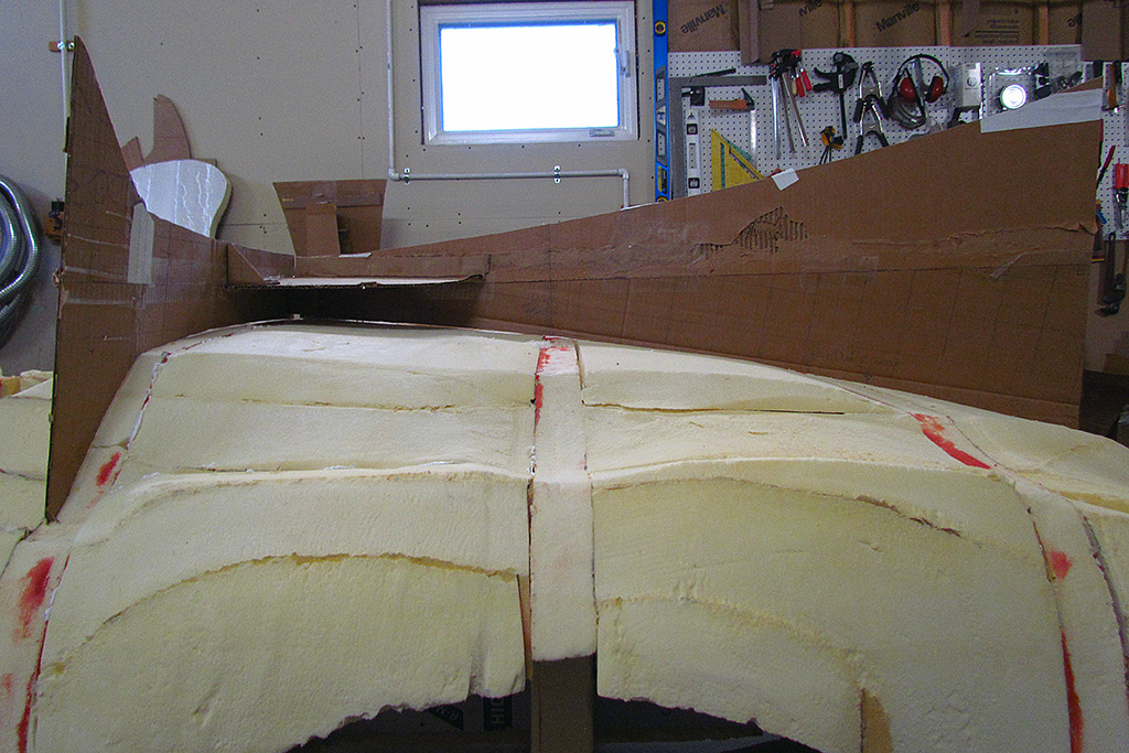
1st ROW - Checking the Shaping
(L) One has to begin somewhere. Contour templates are positioned on the roughed-out body to see how close is the fit. The lower part of the rear fender needs reduction especially.
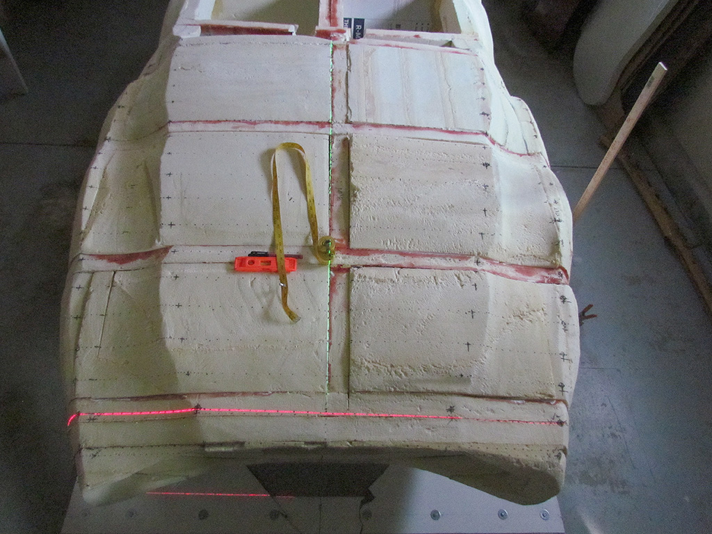
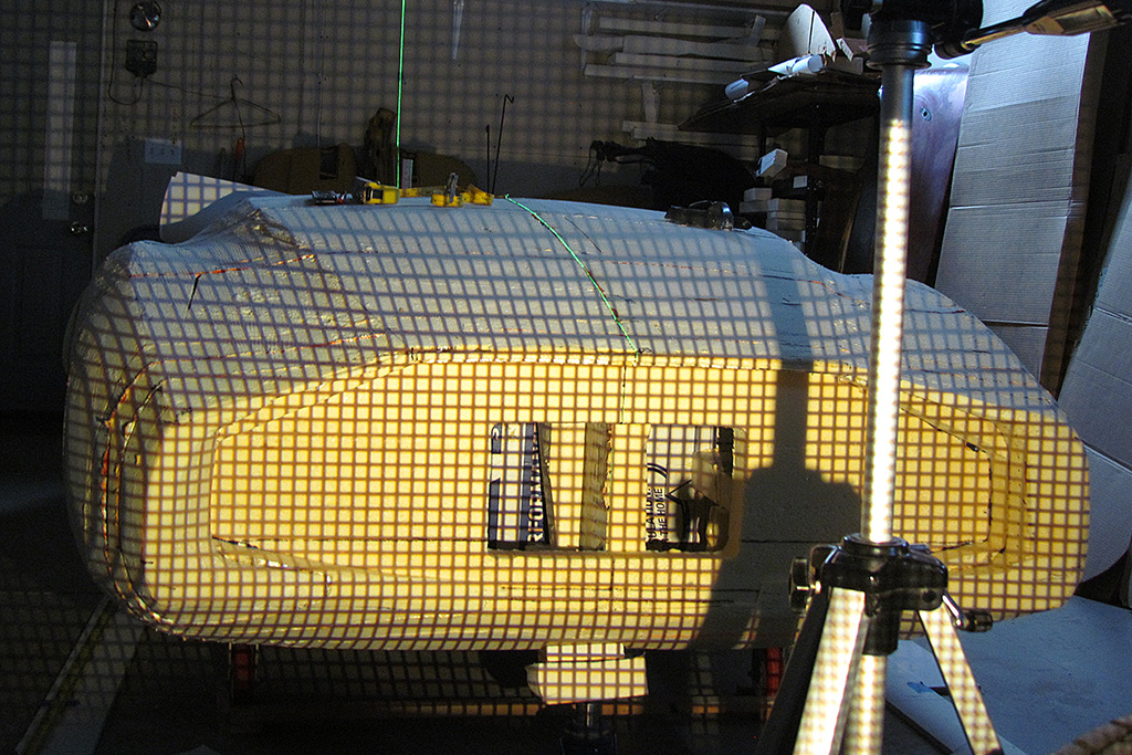
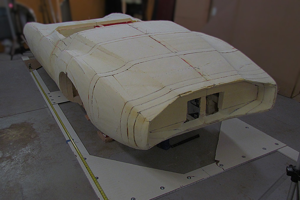
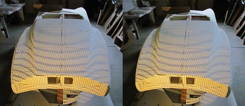
(CL) My experiment projecting a grid onto the body. Here is a straight-on projection onto the rear.
(CR) When seen above, its usefulness shows up. The mismatch between left and right top surfaces is due at least in part to the projector not being centered, although it seemed level. Note the green center line.
(R) Being off-centered allowed the projector to shine onto the outside surface of the fender. Also a useful projection.
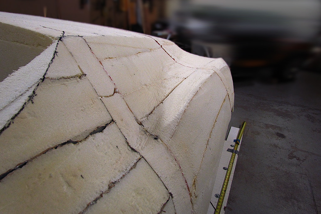
2nd ROW - Refining the Tail
(L) The set of templates for the rear fender - an artful arrangement.
(CL) What works on the driver side must also work on the passenger side.
(CR) A visual check for smooth transitions on the top surface and non-lumpiness on the outside vertical surface.
(R) Looking back at where the rear fender ridge commences from the door. I will slowly work into this point after doing the front fenders.
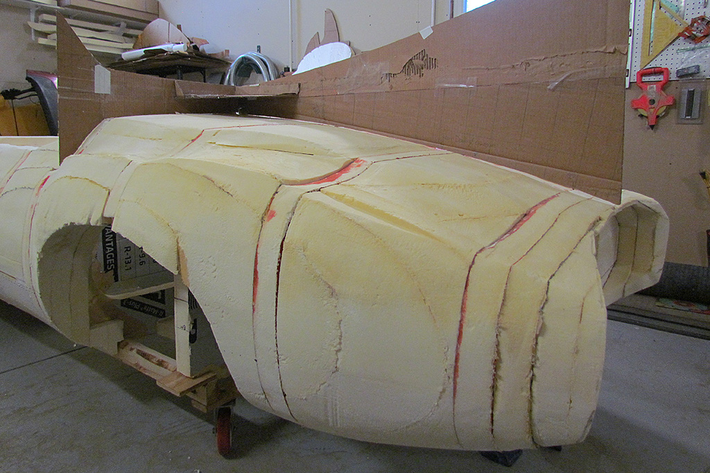
3rd ROW - Beginning the Front Fenders
(L) Fender check - profile view
(C) After the front fender first pass. On this pass, I establish the width position along the ridge line by measuring from the front-to-back centerline.
(R) Another view looking sorta forward.
4th ROW - Laser Test on Fender Ridges
(L) Another test of concept. My ortho drawings show the fender ridge lines as nearly a straight line as seen from the front & rear, and angling outward.
(C) A laser level is set to vertical and locked, and then pivoted sideways to a 29.25 degree angle.
(R) It seems to work and so I trace the path of the laser.
5th ROW - Front & Rear Fenders Tight First Pass
(L) Jumping ahead, the front fender line was next shaved down to the correct height above the wheelbase centerline.
(CL) Then the front fender ridge lines were again located from the front-rear centerline, and the fenders smoothed from the ridgeline.
(CR) I also shaped the front top surface between the two front ridgelines. This turned out to be more easily done than I expected I used the longer, yellow-handle rasp without the handle.
(R) I could feel the unevenness of the surface and shave it as needed. About a half hour of work and it was accomplished on one side.
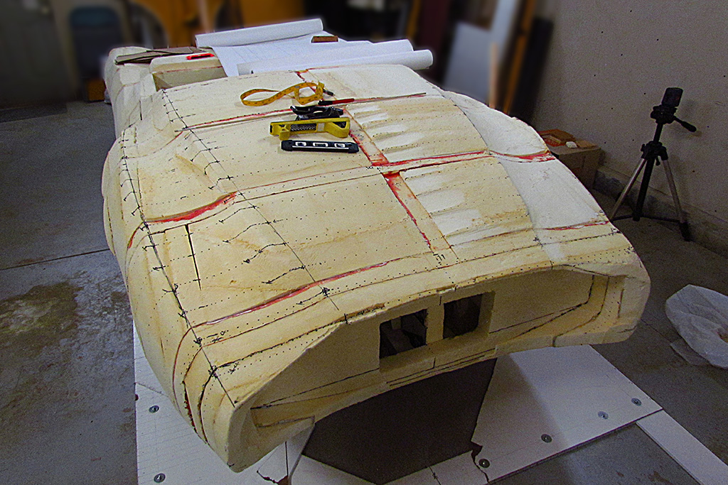
6th ROW - Walkaround
(L) At this point, I have not yet used contour templates on the front end.
(C) It turned out surprisingly well. There is still need for refinement, so contour guides will be next.
(R) It is dialing in!
7th ROW - Feelin' Good
(L) Compare this view to the next one...
(CL) Those fender shapes really stand out.
(CR) Using the laser unlocked and freehand to check the left-right symmetry. Yes!
(R) It has taken ten years to get to this point. I am pleased with the results.
April


1st ROW - Shaping the Cockpit
(L) One evening, I made this simple sketch to show the progression in body design in the early decades of the automobile.
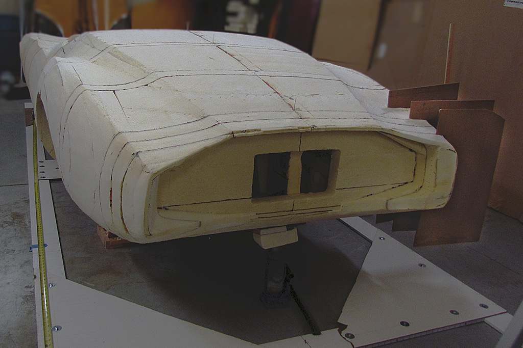
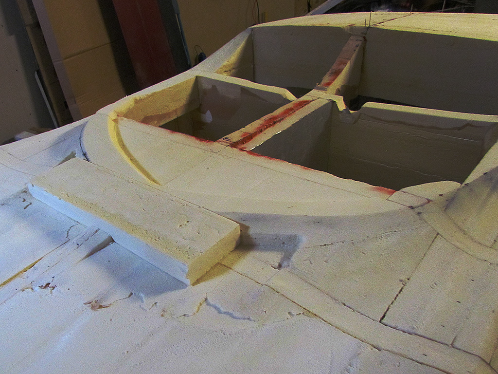
(CL) Beginning work on the ventilation vents. Note how the front peak of the windshield outline drops down. I will have to build that up.
(CR) The vents are carved, but that front peak has to be raised.
(R) I decide to cut it out and glue in a new block of foam and recarve it. This is the old piece coming out.
2nd ROW
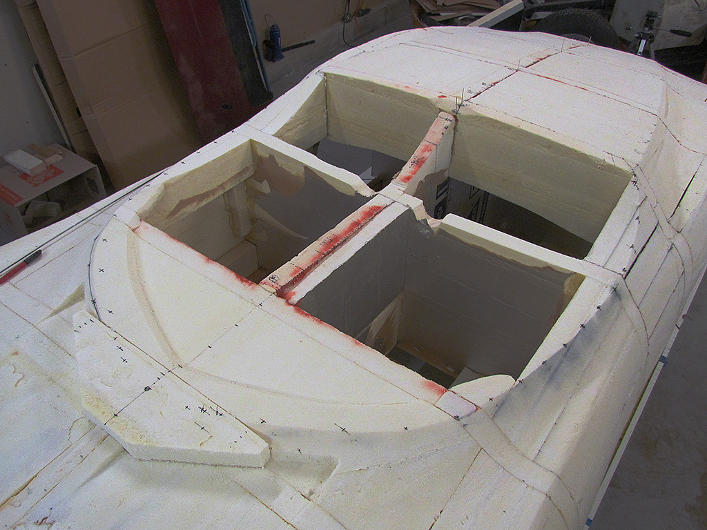
(L) The new block of foam glued in place.
(C) ... and trimmed and marked before carving
(R) Using the laser level to match points left and right.
3rd ROW - Checking Front & Rear
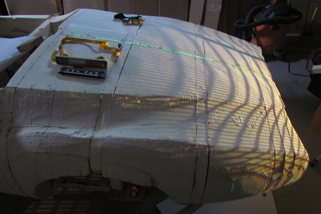
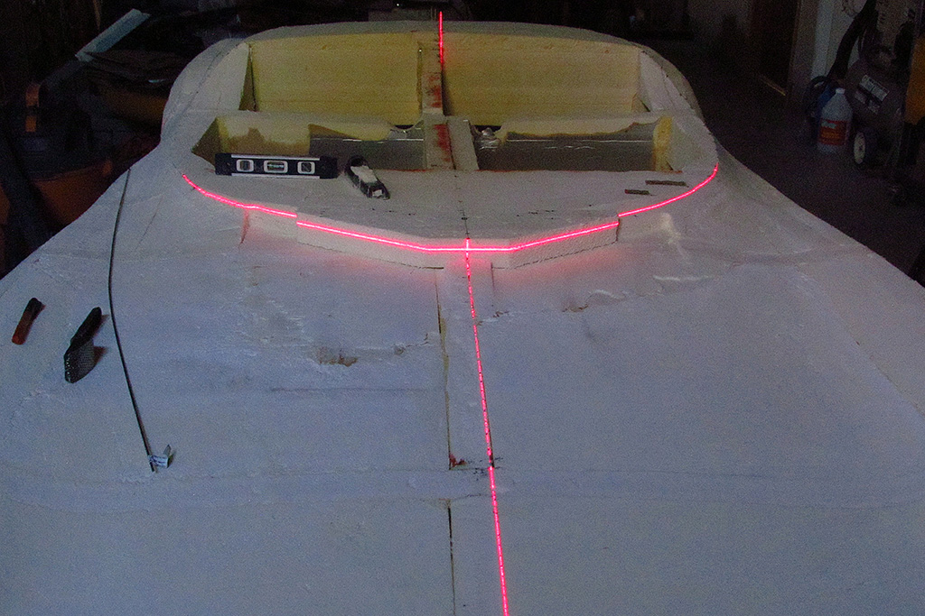
(L) With the body level to check the surface topography, I made a multiple exposure of the laser level horizontal lines. They look like good matches left and right.
(R) Not so good for the rear deck. Those lines are skewed! I will need to check my ridge points.
4th ROW
(L) Once again I mark the rear deck ridge line. I need to sand down to a lower line.
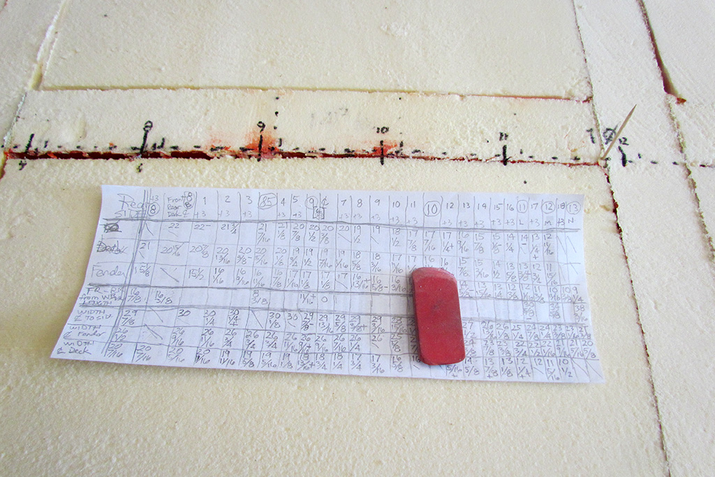
(CL) I also revisit the fender ridge line. Here are my portable notes on dimensions above wheelbase and out from centerline for the front fender.
(CR) The grid slide looks much better now. But I won't use this method again. It is too hard to align the projector and slide.
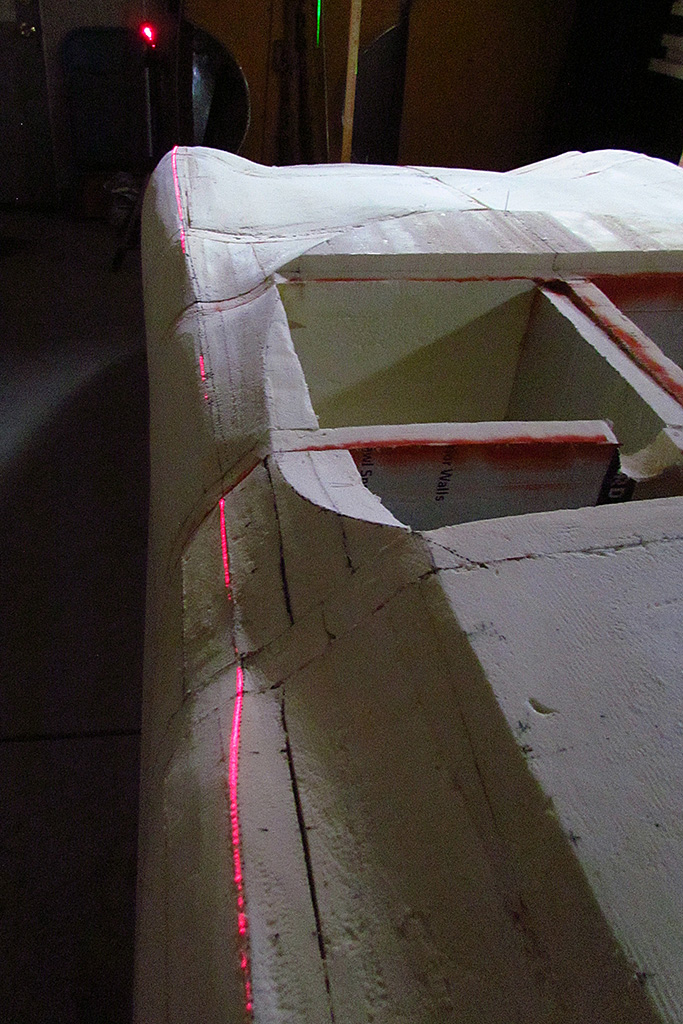
(R) I also reshape the doors to better blend the front and rear fenders and enhance the horizontal crease on the lower door. Here is my laser check for topography.
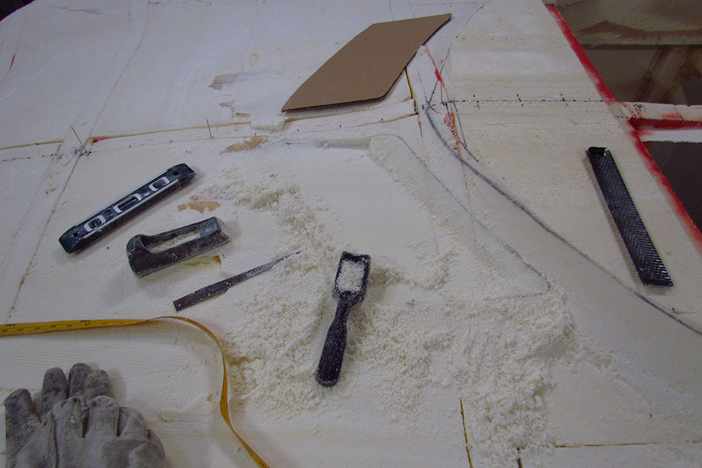
5th ROW - Working with Automotive Clay
(L) Just beginning to sculpt off the applied clay. Note the lumpy texture. It must be worked when applied to stick to the foam surface.
(CL) And here it is after the first pass rough sculpting.
(CR) A side view. I sculpted it by eye at this stage. There is still lots of material to remove.
(R) The backlight shows both the uneven texture as well as the shininess possible with the clay.
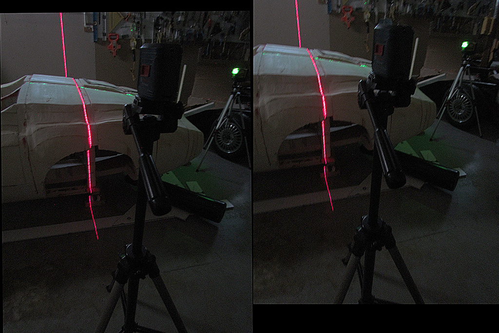
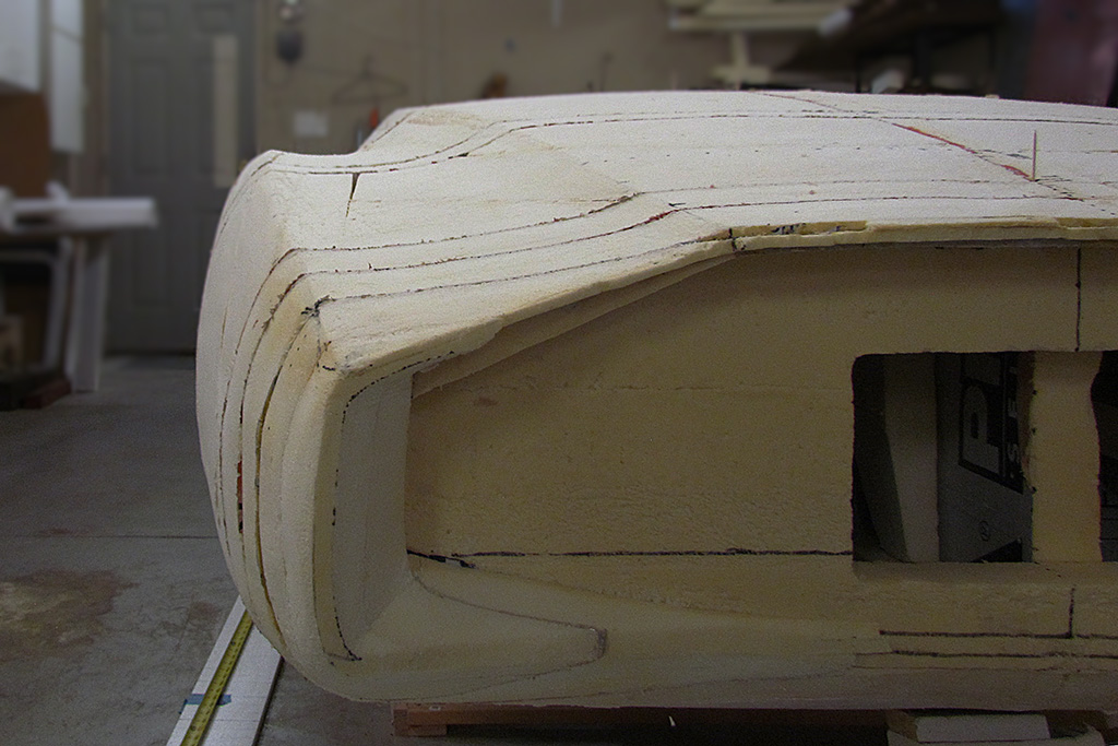
6th ROW - Trimming Out the Rear Wheel Wells
(L) Using both lasers to establish the wheel centerline and the height of the wheel well top.
(CL) An interesting shot with the red laser revealing the body shape along the side.
(CR) Another view, this one showing the two lasers.
(R) And with the well outlined and the chamfer outline drawn. I will have to add material for the chamfer.
May


1st ROW - Back To Work
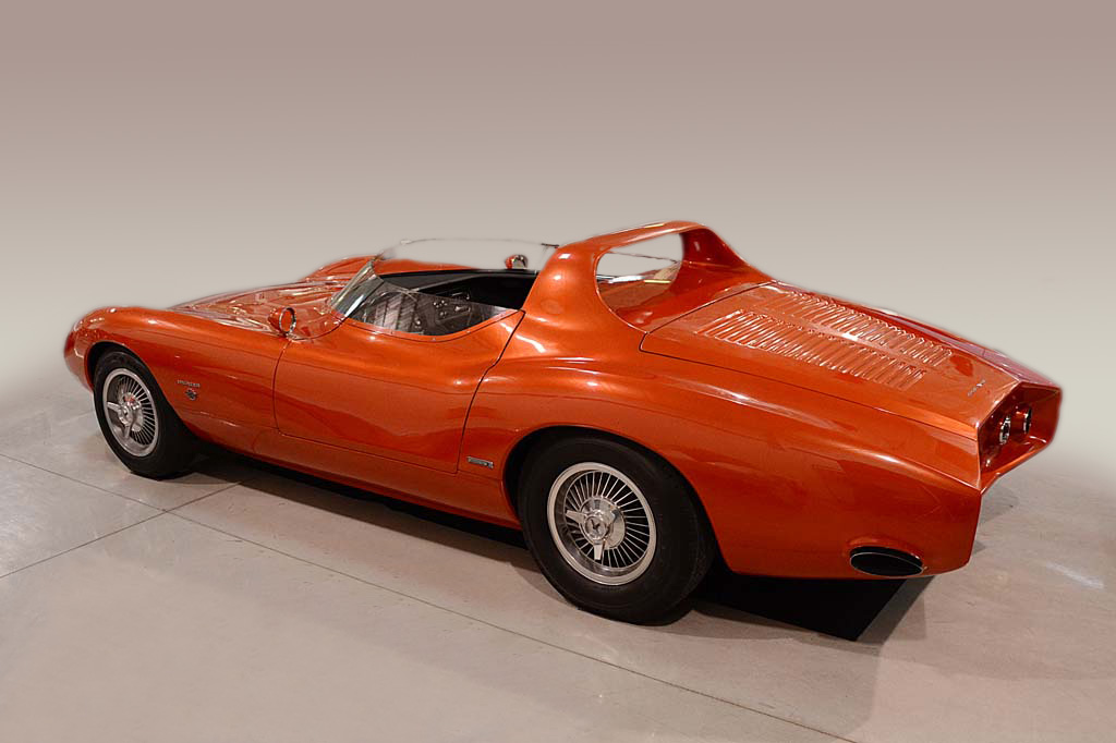
(L) Revisiting my photos of the Actual Article. This time, with the background eliminated.
(CL) The color and the car overall really stands out with the plain backdrop.
(CR) Notice how the reflection lines follow the shape. There are NO straight lines on this body. Except a reverse crease at the bottom of the door panel at the midline.
(R) And a parallel-view stereo image.
June
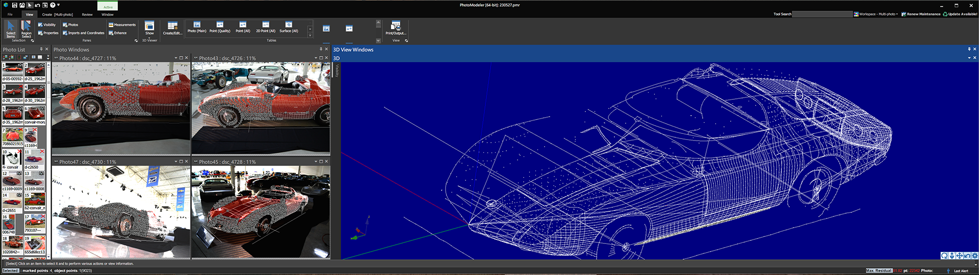
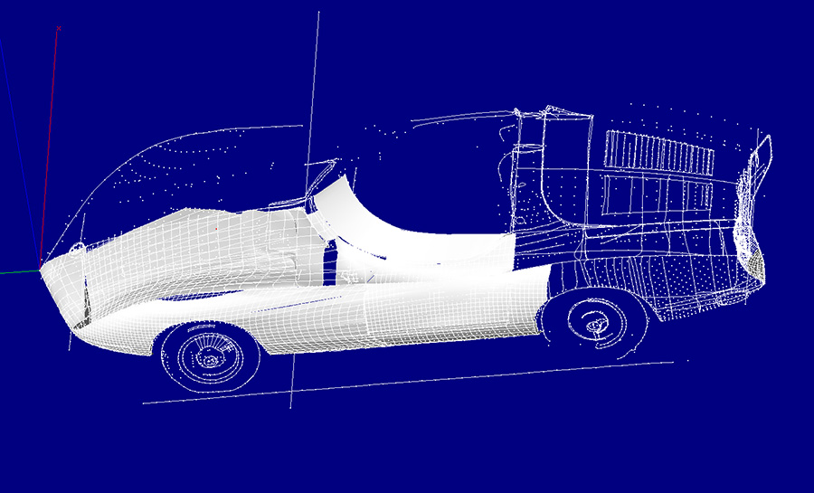
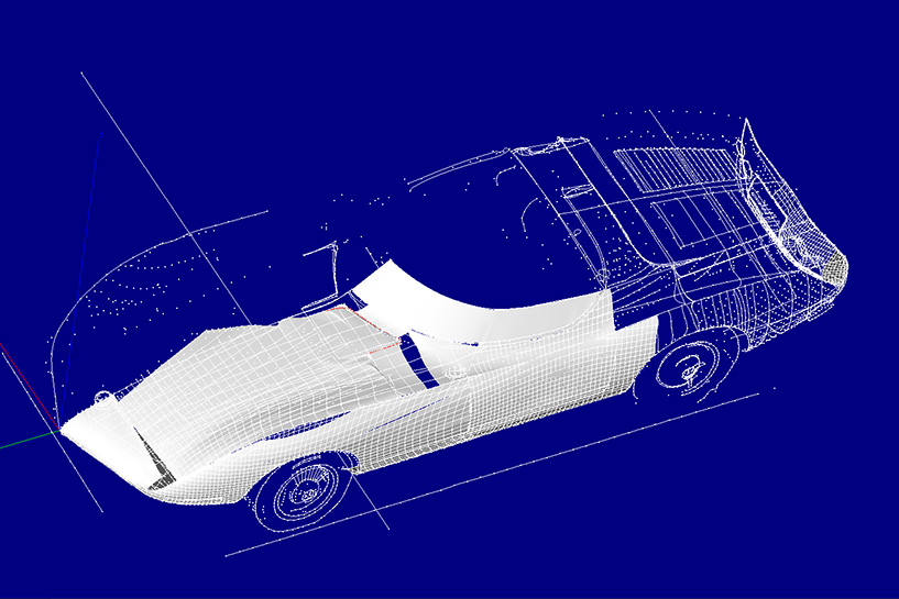
1st ROW - 3D Rework
(L) Here's looking over my shoulder while at work on the 3D Photomodeler file. I plot points on my photos taken of the real car back in 2016 and 2019, as well as photos found on the internet.
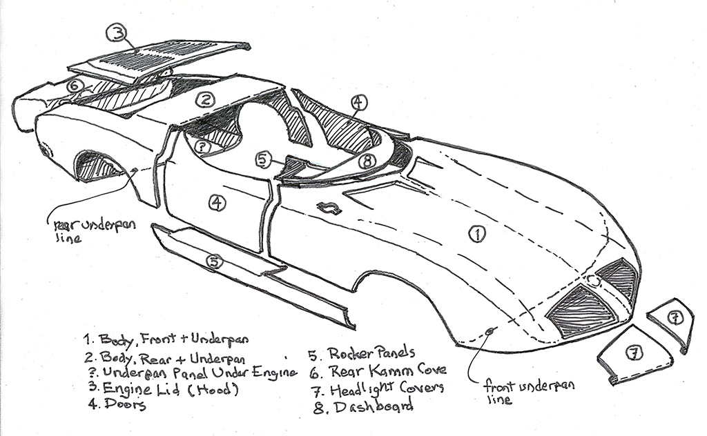
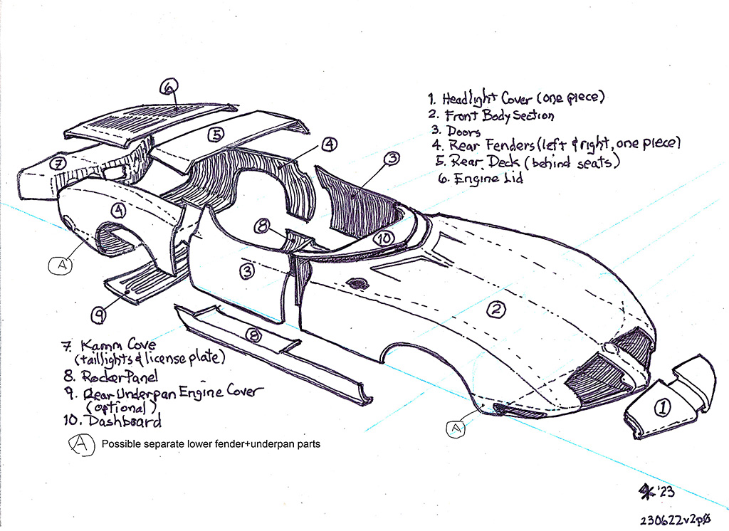
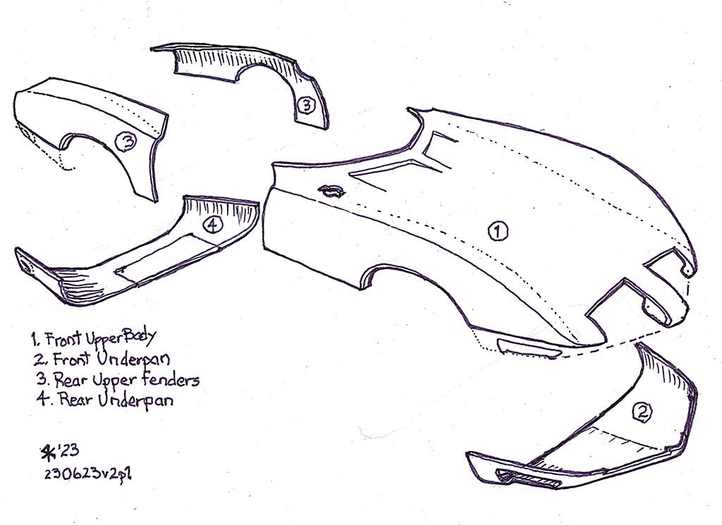
2nd ROW - Thinking Ahead on Fiberglassing
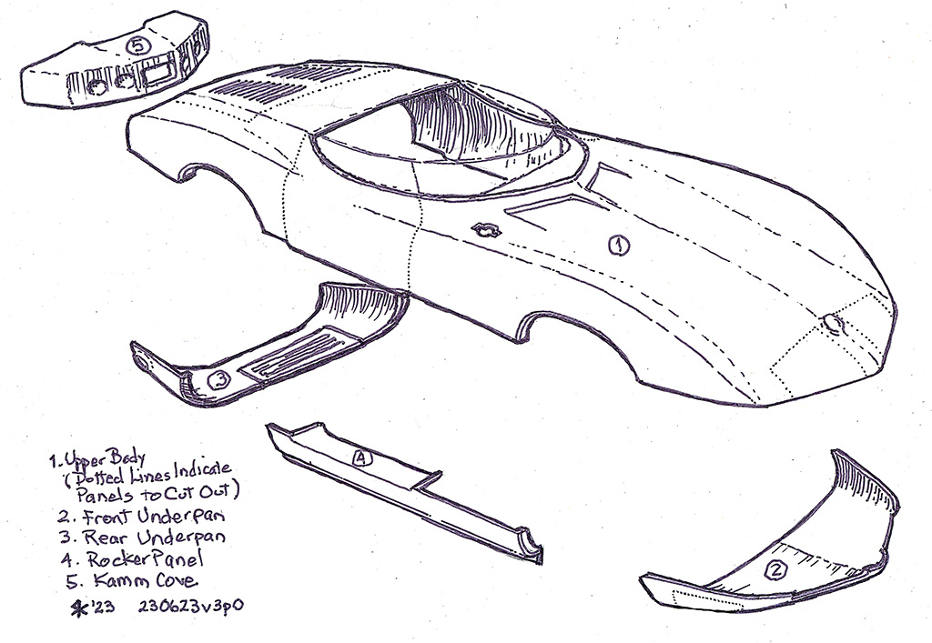
Here are 4 sketches thinking out how the body will be broken into parts, or panels:
(L) Version 1 - Keeping the major front and rear body sections as single pieces.
(CL) Version 2 - Starting to break those sections into more parts.
(CR) Version 2.1 - The same, really. Only this shows the major new parts.
(R) Version 3.0 - On the advice of someone who has been there, treating the entire upper body as one part. Once that is attached to the chassis, then the parts & panels are cut apart. This better maintains their alignment onto the car.
July
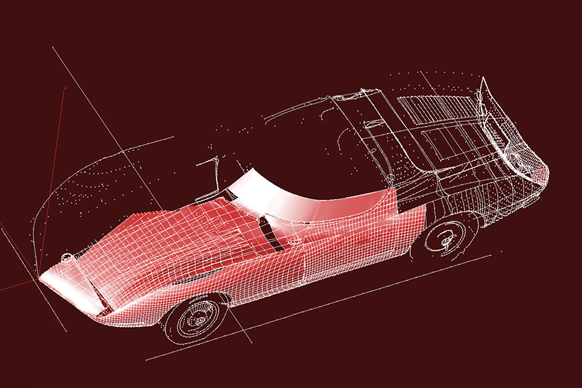
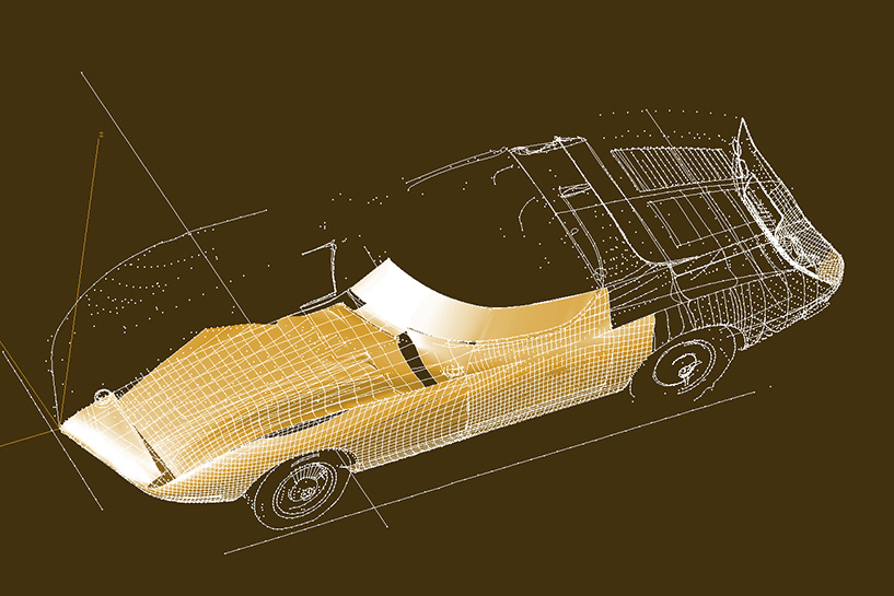
1st ROW - Evaluating body color in Photomodeler
(L) I was curious how well I could use the surfaced digital model from Photomodeler to evaluate what color to paint the final car.
(CL) So I explored a couple of views and chose this one. Here is what it looks like in Photomodeler. It sorta looks like silver
(CR) But a candy apple red is close to what the real car looked like originally - sorta like this.
(R) I was intrigued by a bronze or gold finish, so here is an approximation. The red and gold versions were created in Photoshop using the HSL colorize slider.
August - November
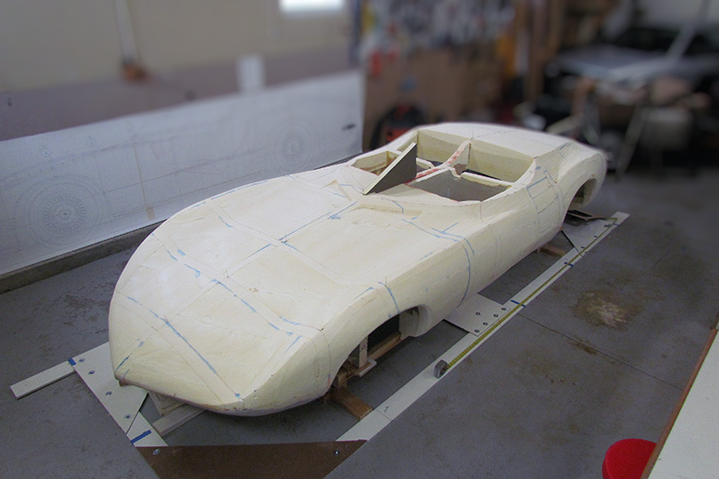
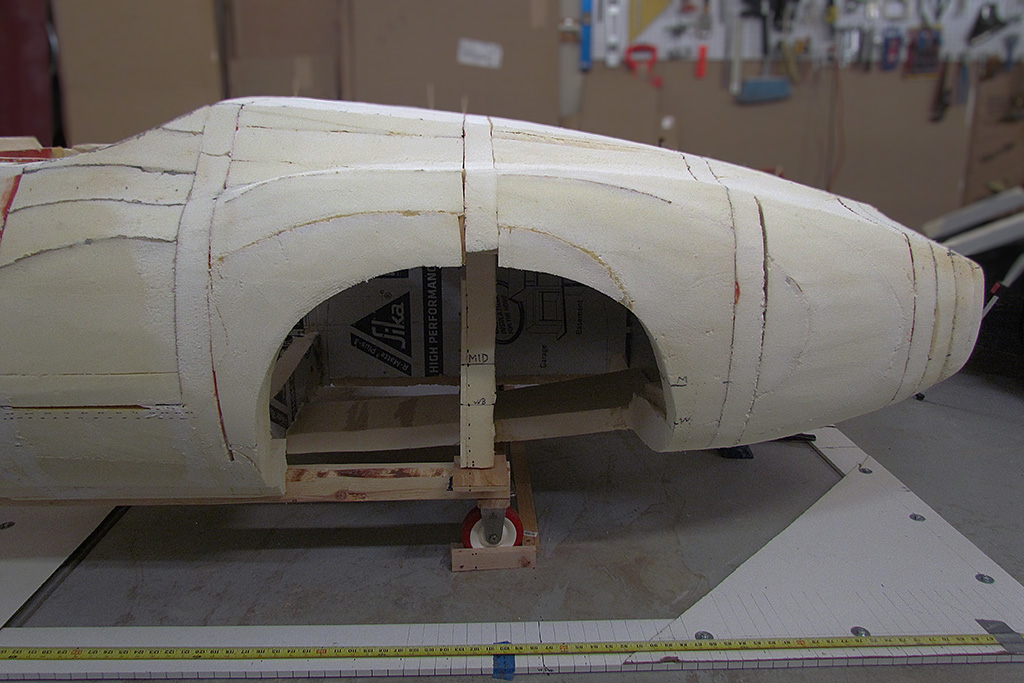
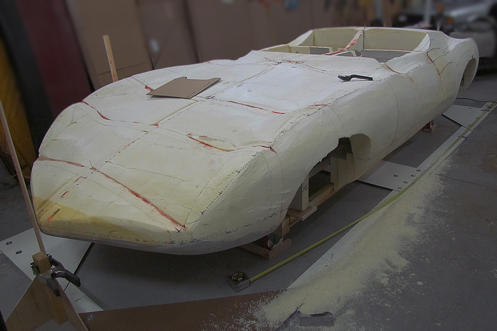
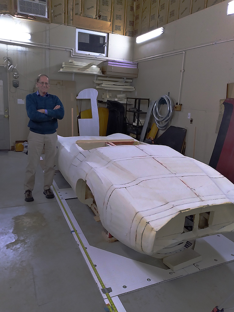
1st ROW - Status report - a Walkaround
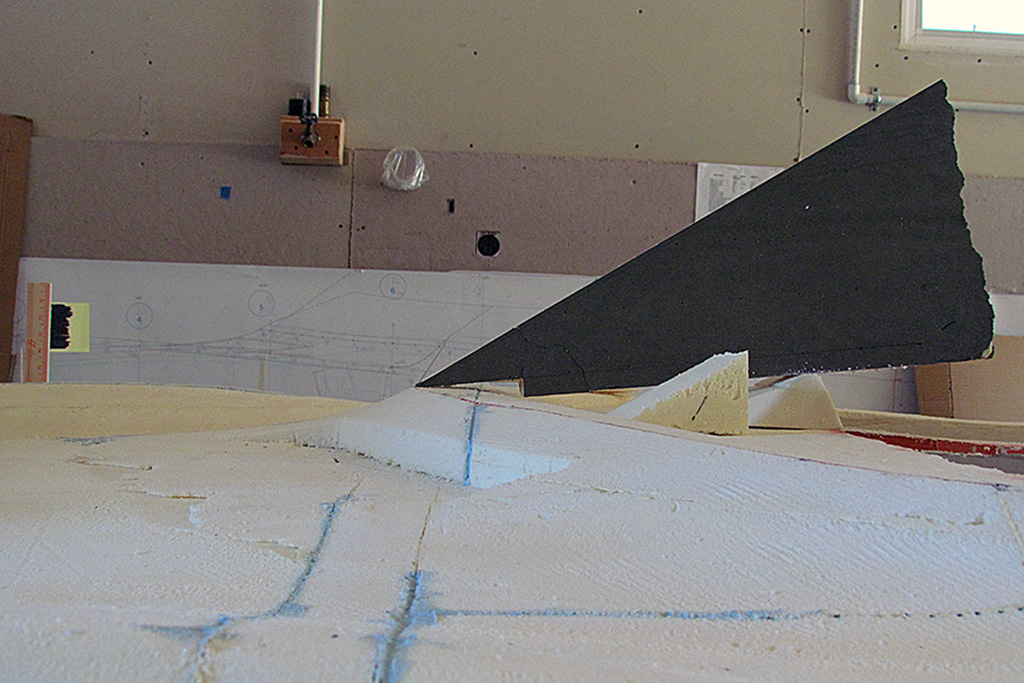
(L) 3/4 front view. Note the dark gray triangle on the dash. That is the intended angle of the windscreen/windshield. That angle doubles to more upright by the door front cut line.
(C) The angle is about 30 degrees from horizontal.
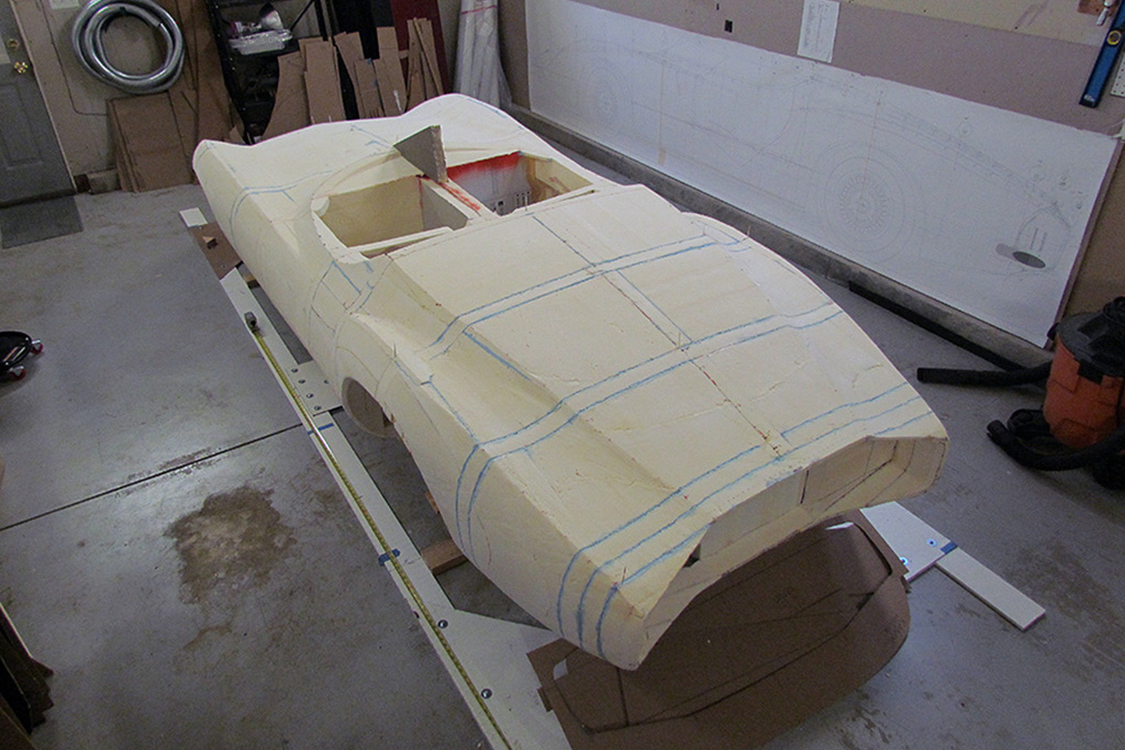
(R) 3/4 rear view. Note the blue seams. The seams were filled with foam glue to help secure the sections together. After all the carving, some panels were getting thin with less contact surfaces.
2nd ROW - Establishing the Length
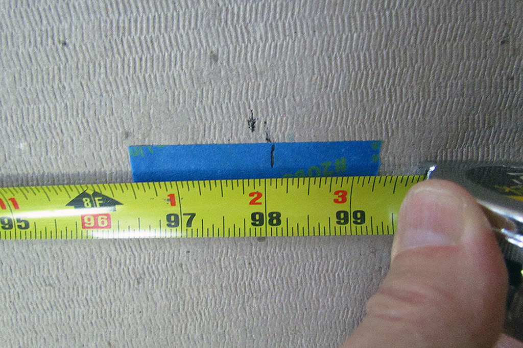
(L) With care, I establish the wheelbase center left and right by placing a true vertical stick at wheelbase centerline.
(CL) next comes the lasers, red (wheelbase) and green (centerline). Note the red line on the right wall and the blue tape to mark where the laser falls at wheelbase.
(CR) It took a 3rd laser in the front to confirm the front/back centerline from which all measurements and alignments are made.
(R) And this is how close I came to matching the published wheelbase of 88". It says 98 but the tape measure was set to 10 at the front wheelbase centerline (98 - 10 = 88).
3rd ROW - Evening-Up the Kamm Tail
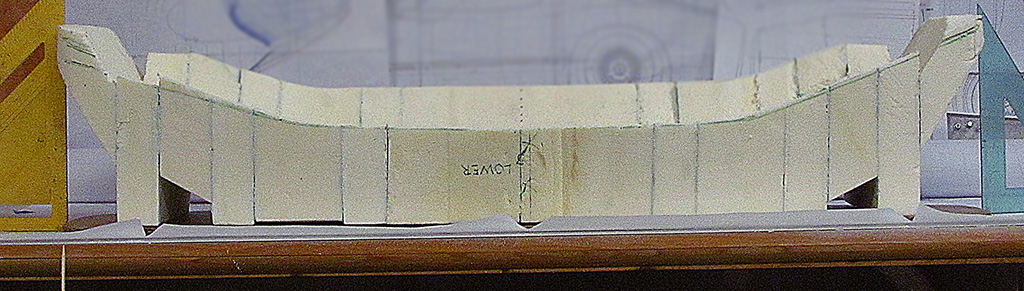
(L) The Kamm tail where I last left it.
(C) The problem is that, after careful measurement, the driver side is longerthan it should be in distance from the nose, but the passenger side is short by about an inch.
(R) So I trimmed back the driver side and added a fill piece to the passenger side.
4th ROW - Carving the Kamm Cove -- 1st Attempt
(L) I started by glueing four trimmed foam blocks together. I decided to use commercial strength white glue and added the weight and let it sit for nearly a week.
(CL) There was still white glue seeping from the seams, but it held together. So I attempted to cut into it to match the shape and outline, before carving into it to create the concavity.
(CR) The cut was not real accurate or easy to make so. But worse than that, the block were not drying and could be pulled apart. I decided to cut my losses and start again. Time to step back, step outside, breathe outside air, and do something else.
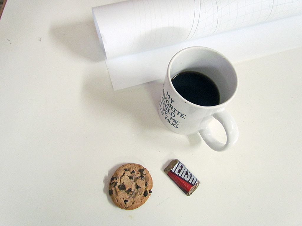
(R) Here's what charges me up when I'm less than motivated.
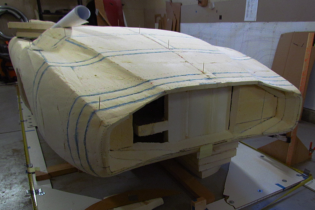
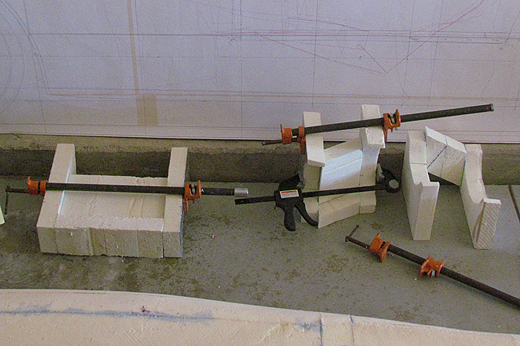
5th ROW - Carving the Kamm Cove -- 2nd Attempt
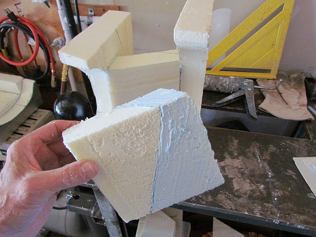
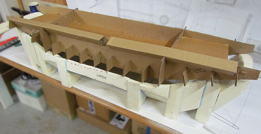
(L) My next approach was to generally replicate the shape of the cove and use contour-shaped foam blocks to guide the shaping. Inbetween the blocks I would use simple, 2" thick rectangular filler blocks that would be sanded down and into shape. For example, here's an assemble section, with top, center, and bottom pieces glued onto a contour-shaped foam piece.
(CL) I begin by building up the different sections. I am using carpenter clamps to pressure them together as they dry.
(CR) I used the blue foam glue this time to assemble them. It holds better then the white glue and actually dries predictably.
(R) Then the sections are then clamped together from contour-shaped piece to contour-shaped piece.
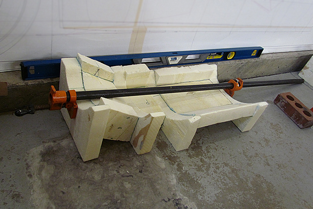
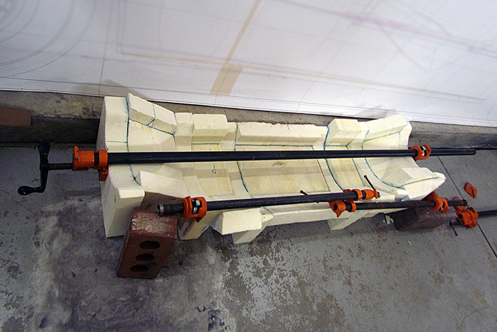
6th ROW
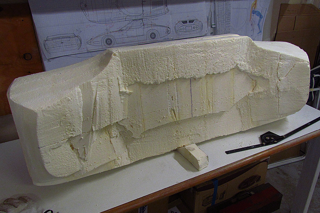
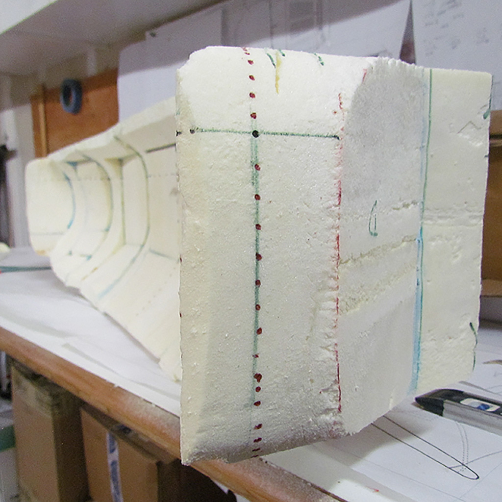
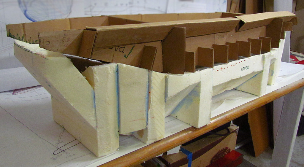
(L) And within a week, I had the entire Kamm cove shape glued together. Note the double clamps. That's what one does when one clamp is not long enough.
(R) Here is the cove shape before shaping. Also shown are cardboard patterns used to check the shape of the Kamm edge lip, top and bottom, plus an actual lenght outline of the edge lip. It was created in Illustrator. Upon running it around the lip edge of the current body, it turned out to be slightly longer.
December
1st ROW - Checking the Kamm Tail/i>
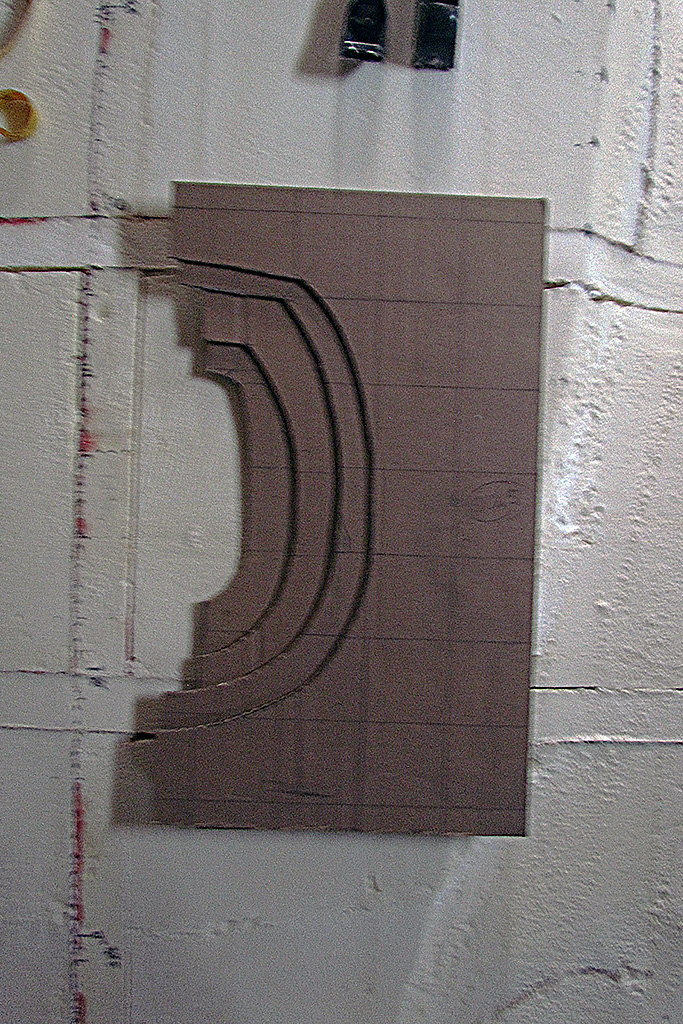
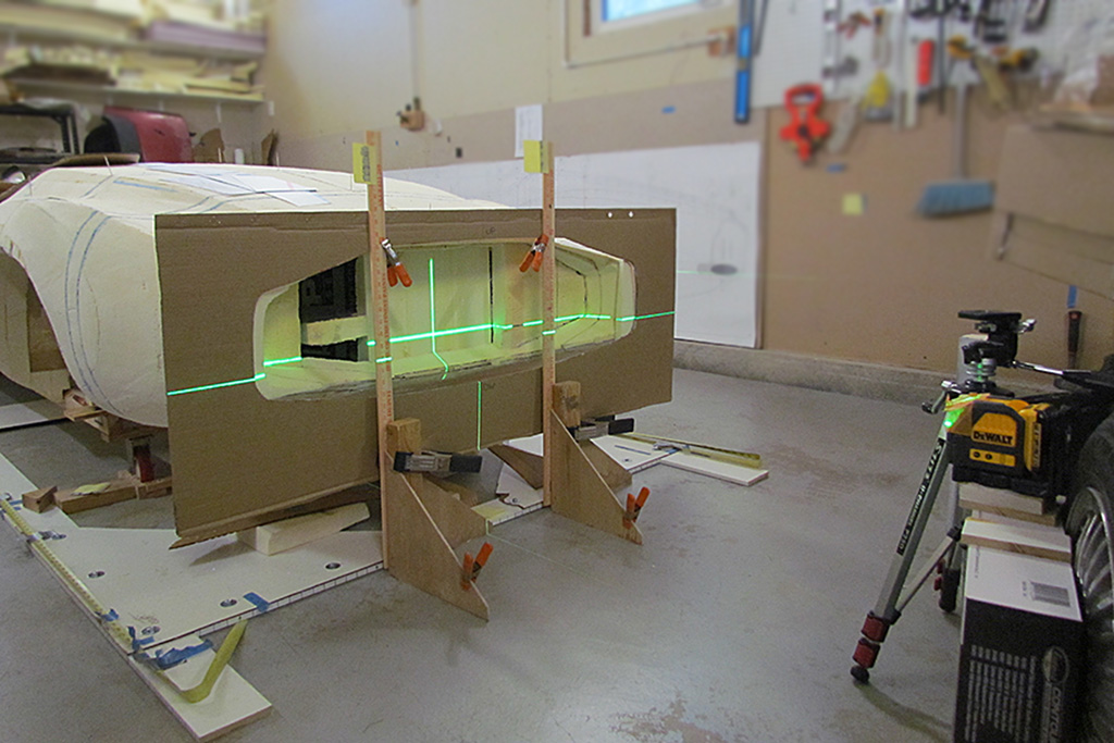
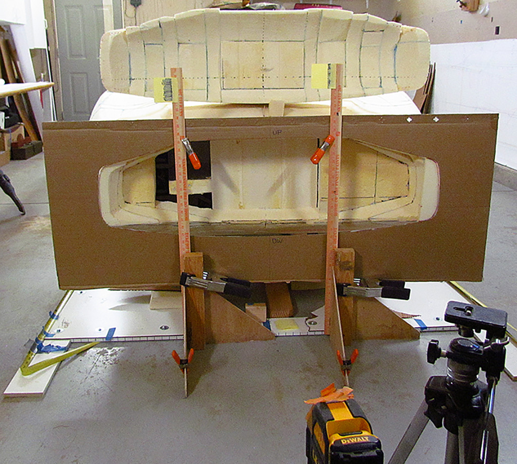
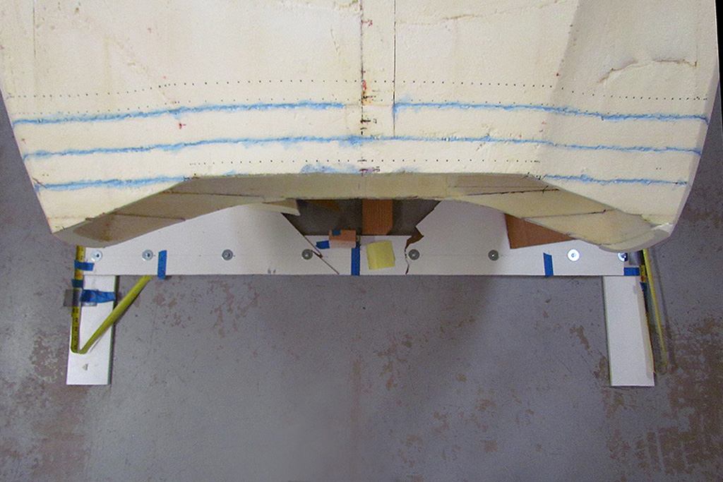
(L) I created a cutout of the ortho view of the Kamm cove to use to create the outline on the body that must be hollowed out for the new foam cove. I align it using the laser level and center it on the previously established front/back centerline.
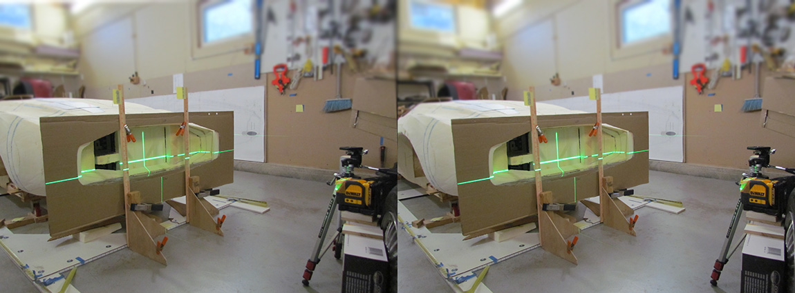
(CL) Just for fun, a stereogram of the setup. (parallel-viewing method)
(CR) An end-on view.
(R) Top-down view of the existing body shape. The dotted lines mark some of my contour station lines.
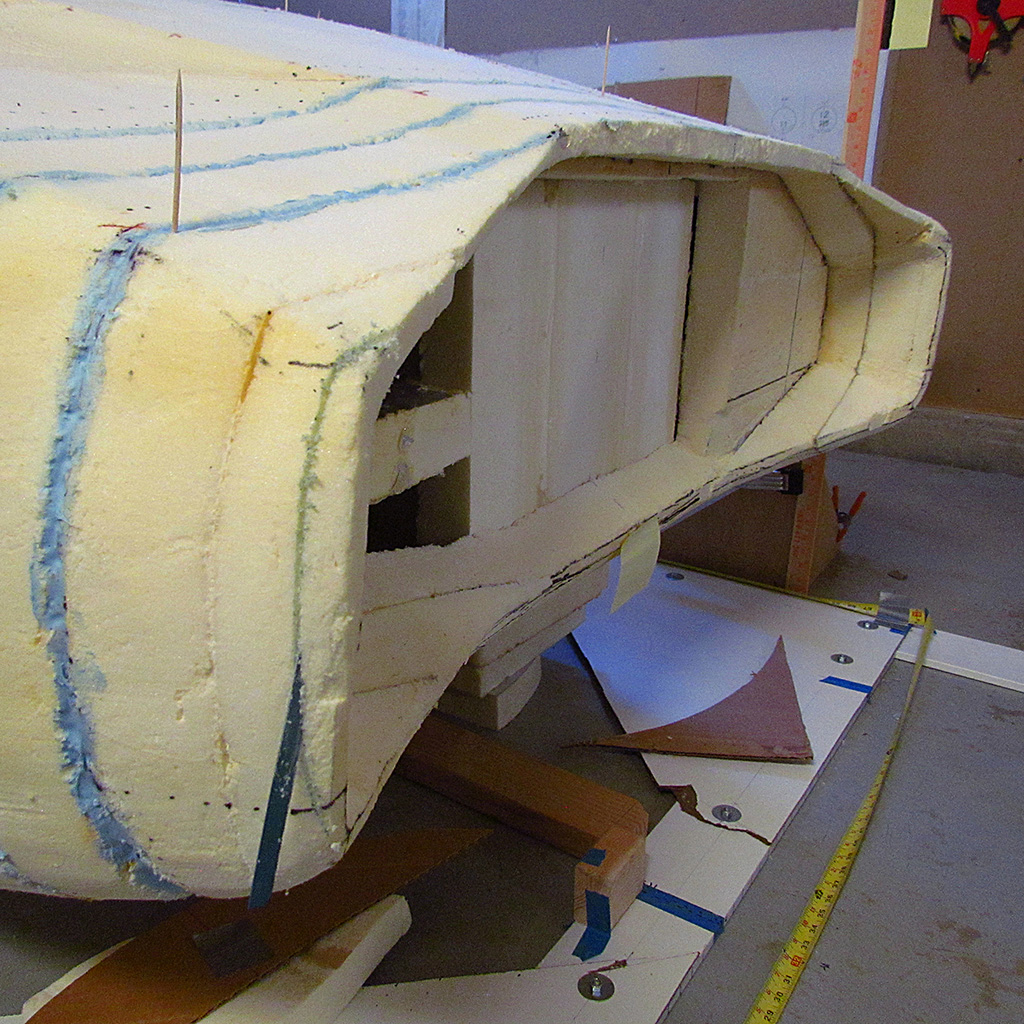
2nd ROW - Shaping Kamm Cove Outline/i>
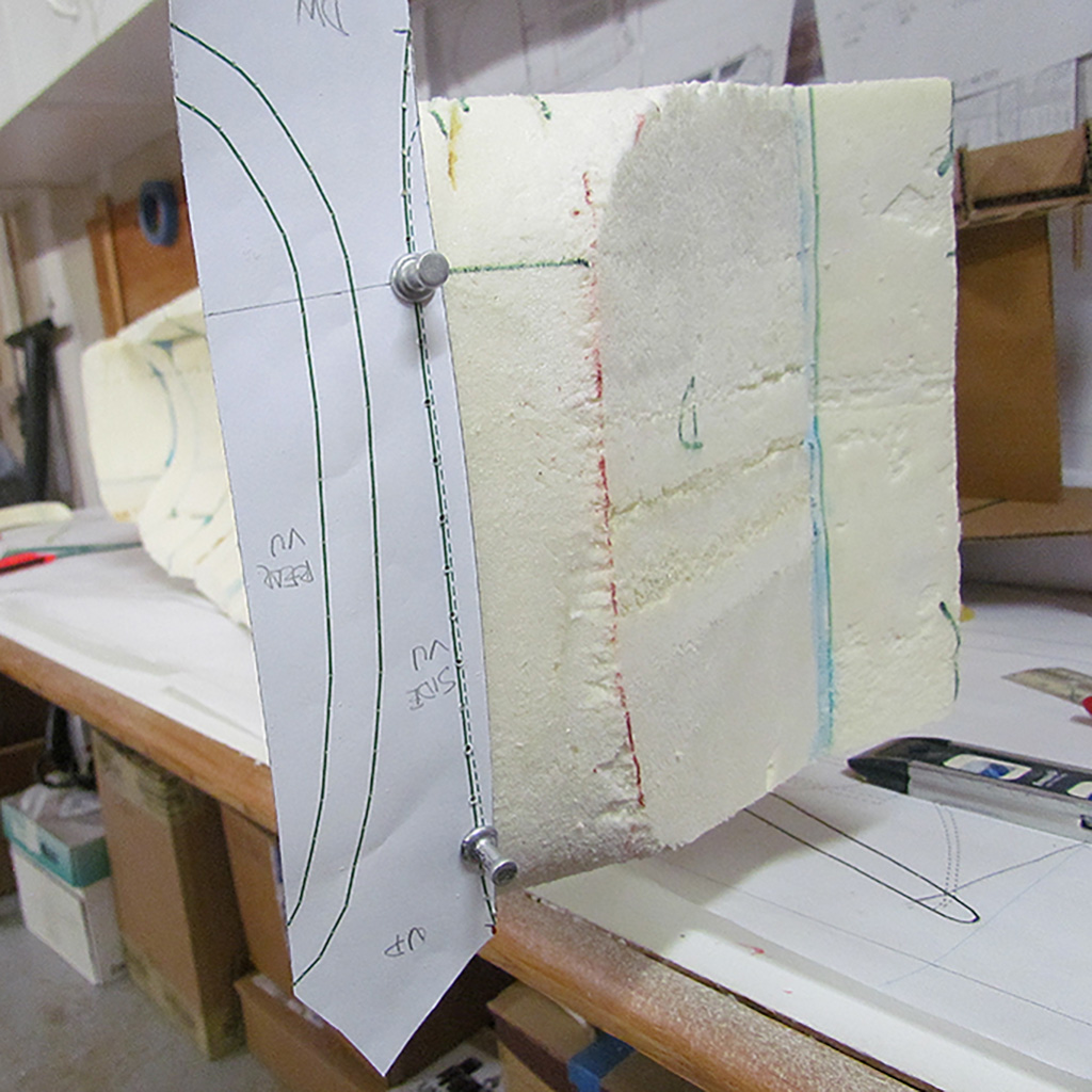
(L) Back to the cove shape. The first step is to make sure the shape is trimmed to the cove outline. I shape the outline until the cardboard cutout can slip fit over the shape. Next is the end shapes as seen from the side view. They are slightly curved and this is harder to transfer to the foam shape. Here the end shape is traced onto the foam from a paper pattern.
(CL) The dotted line marks the cut needed.
(CR) More work to be done for the top-down view. Note that the upper lip protrudes much more than the "lower" lip. I will add foam to fill missing sections and shape to the contour.
(R) Here is where I tested the actual lip perimeter on the cove. It's close, but the front blue section is too long.
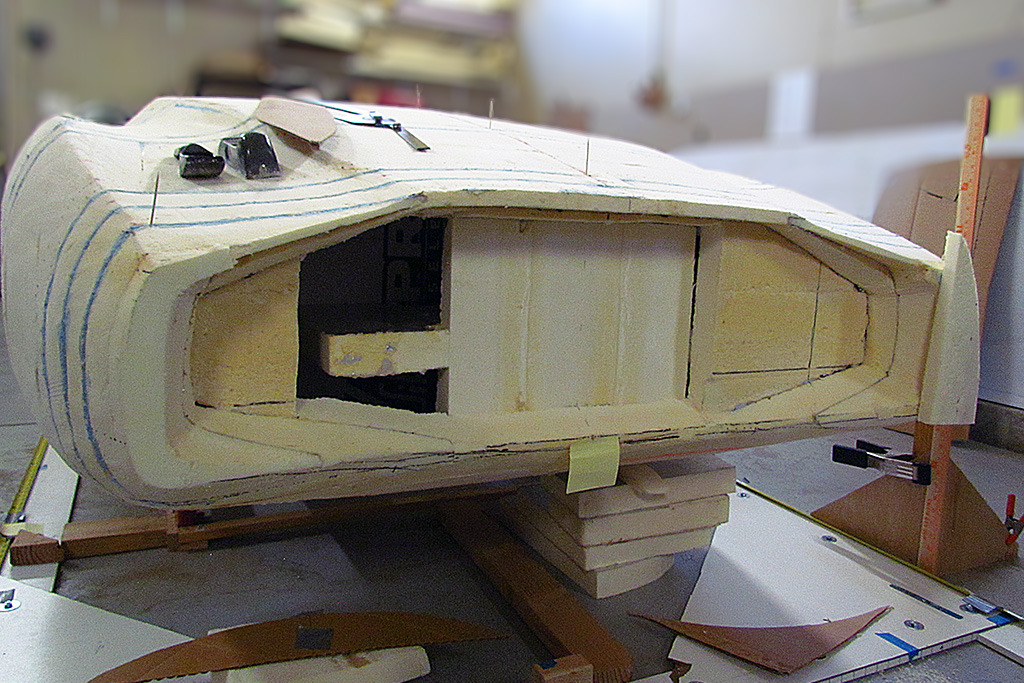
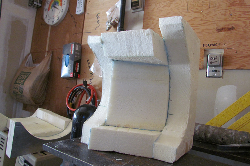
3rd ROW - New Pattern to Check Concavity
(L) Thinking ahead, I decide to create a cardboard pattern that will insert into the cove concavity, to aid me carving out the cove. Here is what I came up with.
(CL) After shaping and carving out the cove, here is how it fit. Generally good. . .
(CR) . . . but not exact on the ends.
(R) Also, it cannot tell me how deep I need to carve the cove concavity. Which leads me to my third attempt, which will start the new year!