Contact: Rich Kurz Page content last updated December 3, 2024
The Construction Diary
2024
JANUARY
Did I say a third try making the Kamm cove?!?! I DID!
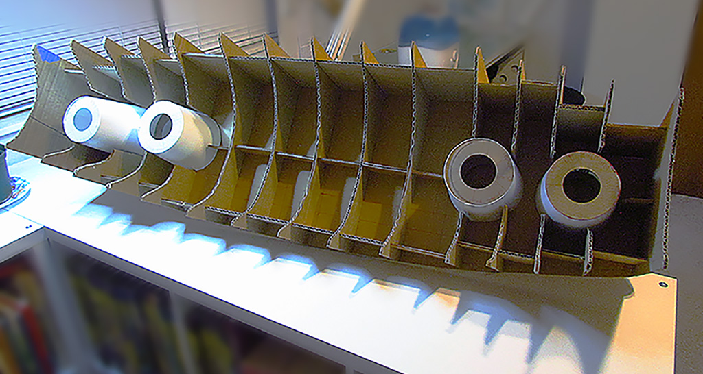
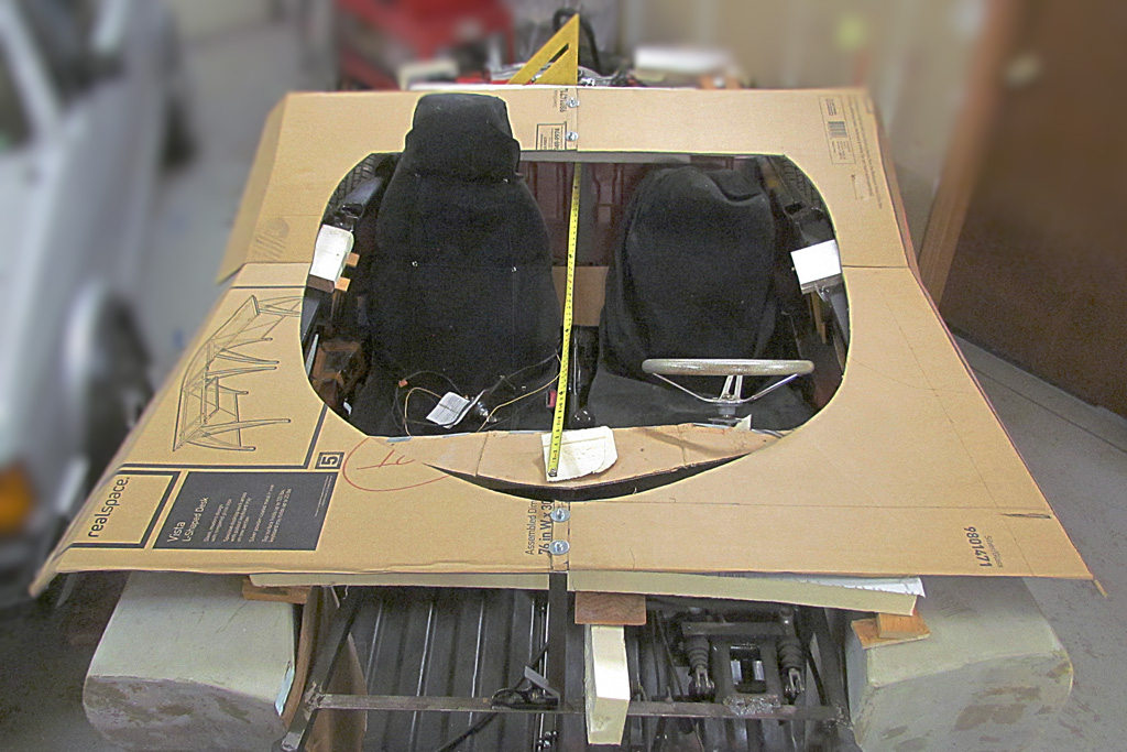
So, while making the cardboard contour template to fit inside the Kamm cove foam piece, I realized that I was also making the contours to create another Kamm cove.
Only this one would be more accurate, having more contours.
To then create a finished piece, I could spray insulation foam between the contours and sand down to shape.
And it would begin from the accurate cutout of the Kamm cove outline, which when all is done, I could then simply insert into the tail of the foam body.
This struck me as a more accurate, easier to be accurate, and easier to mate with the foam body approach.
It was well worth trying at this point.
So I glued the cove contours onto the Kamm outline cutout.
That done, the next step is to make the taillight cones to glue down on the Kamm outline.
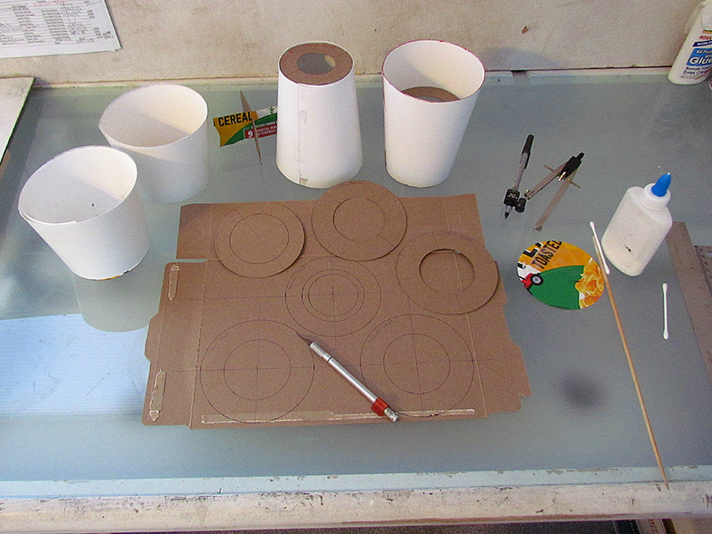
I laid those out, having plotted my cone shape from my 3D drawings, and laid out the shape on some thick, glossy card sheet.
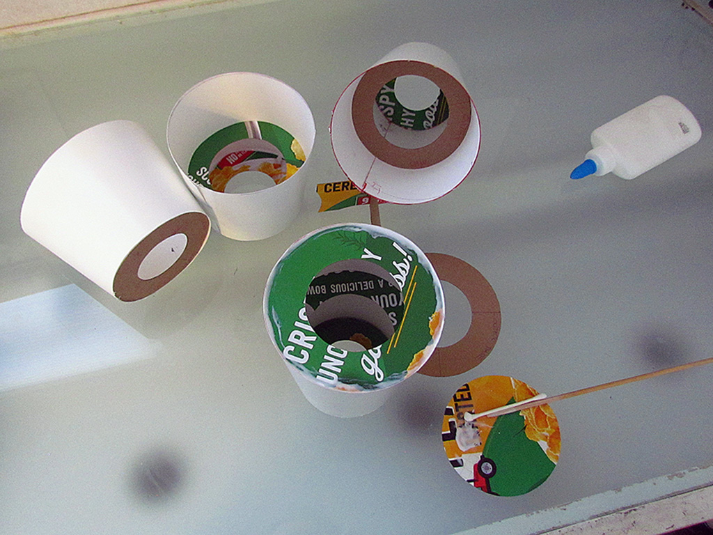
I made it long enough to wrap it twice around. Then I cut out three diameters to glue inside the rolled up shape at the top, middle, and base.
That done, I cut out the placement positions from the contours and inserted the cones, and stood back and studied what I made.
It did not look right. The outer cone look too tall and too narrow at top, while the inner cone looked too short and too wide at the top.
Back to my drawings and refining my 3D points and using my photos of the car to derive the shapes, heights, and placements.
Slowly, painfully slowly, I am settling on final dimensions for the taillights.
It is frustrating and I have to admit that I am stuck in this muck.
But I must come to conclusions I can live with.
SIDEBAR: In Search of the Lost Color
When I saw the original car in 2016, I was struck and intrigued by the paint job on it.
The car from certain angles glowed!
It was more orangey than I expected, too.
So I wondered, 'what WAS the original color? Surely what it is now was not it!'
I could say that because I read notes in the GMHC library saying it was repainted at least once after the rollbar was attached.
And the underside shows definite overspray matching the current color.
I later confirmed the current paint job was ordered as a special refresh treatment under the watch of Ed Welburn when he was the VP of Glbal Design (2003-2016).
Thus began a Quixotic "Impossible Dream" of matching what was no longer.
There are a number of color photos in the GMHC collection that show the pre-rollbar car.
One could match the color in the photos, but you must realize that even with a color card, photo pigments are not the same as paint pigments.
But it did look like the photos showed a color redder - less orangey - than the current paint job.
I thought my best bet was to contact former designers who might remember the car as it first appeared.
There are not many, but they were gracious to me to provide some recollections.
It's a good idea, but subject to possible fading memory and personal preferences.
Of course, they are practiced, experienced professionals and experts in this matter.
One it wise to give their opinion weight.
Mostly, they could tell me what modern colors it was NOT!
But one even sent me a custom painted item with his best guess at the color.
It is good enough that, in my opinion, it is the closest match so far.
Another approach was to locate cars with the same custom GM paint job still on them and get a color reading.
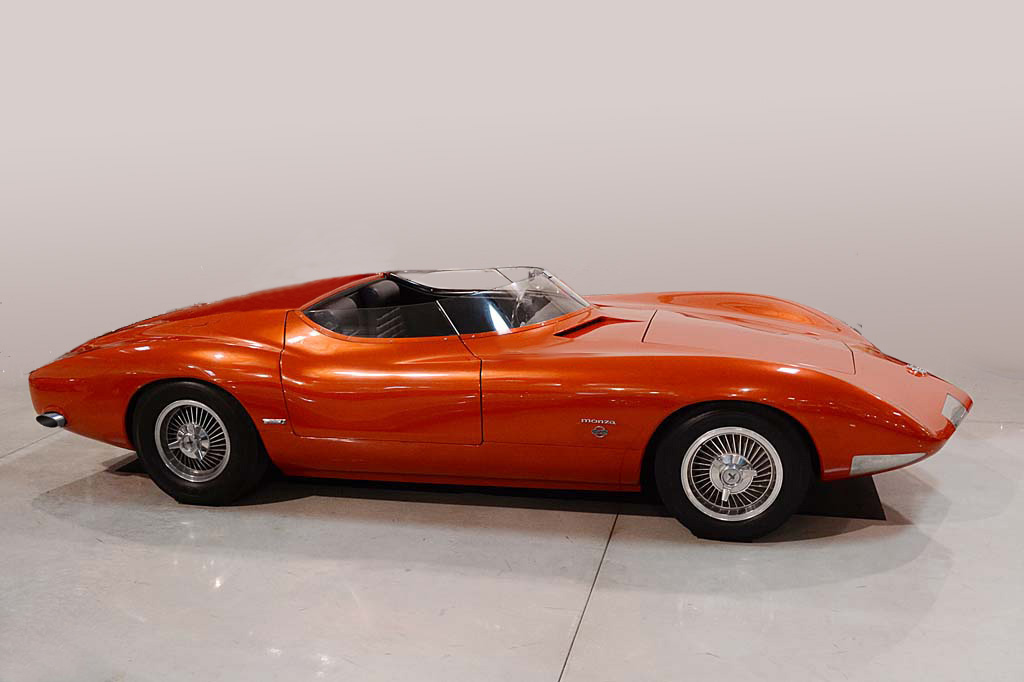
I found a photo of both the Monza SS and a special Corvette made for the 1964-65 New York Worlds Fair.
In the photo, they looked very close in color!
The Corvette today is at the Pierce-Arrow museum in Buffalo.
With their permission, I arranged a color reading with the local PPG supplier.
The spectroscope only identifies the closest color from the PPG library of over 2000 colors.
It resulted in a close comparison, but not exact, as can be seen here.
I compared a chip with the current Monza SS on my 2nd visit, but it did not match even closely.
I started desparing, and decided to just find something that struck my idea of the color.
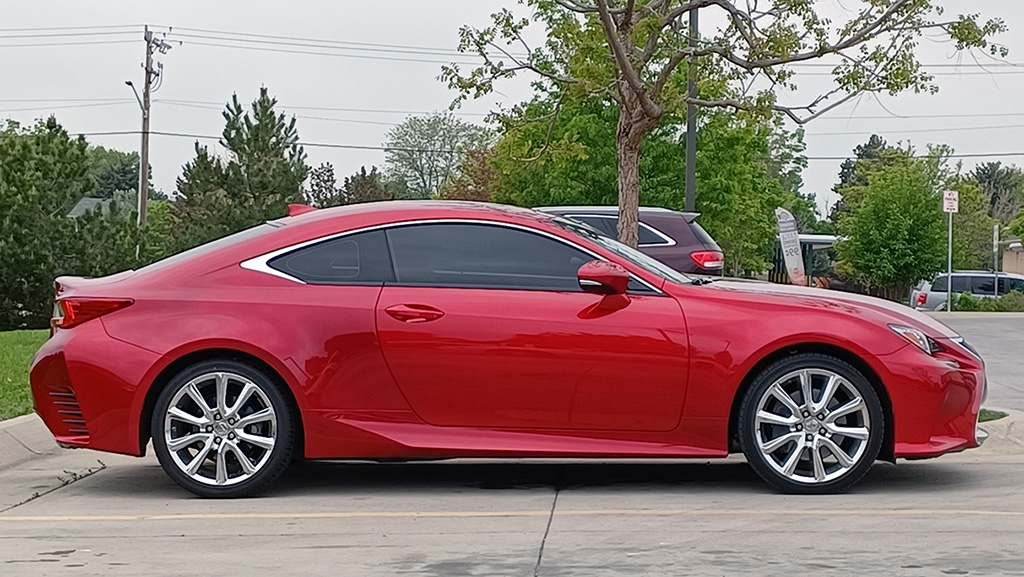
Jump forward a couple of years, and I was put on to one possible modern color that seemed close according to those retired designers.
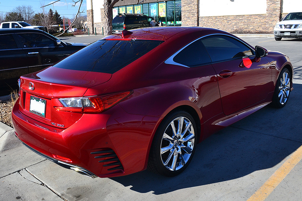
It was not Mazda Soul Red Crystal 46V, but Lexus Infrared Metallic 3T5, a 3- (or maybe 4) stage finish.
And lo, and behold! a Lexus SC 350 showed up regularly at a nearby car parts store.
I would be able to meet its owner, study it and compare paint samples to it.
So next I begin to learn about how custom paint jobs are done and by doing them.
How DOES one do a candy or a tri-color, or a pearlescent or an irridescendent??
July 25, 2024 Update:
One retired GM designer I have communicated with suggested that in his remembrance, the original color on the Monza SS back in the day may have been a Firefrost color.
In 1963, the Firefrost paints were introduced on the top-model Cadillacs exclusively.
There were five colors available, including a Firefrost red.
But a custom shade of red could have been formulated for the Monza SS.
Firefrost used a special aluminum flake in the paint to give it a specail brightness quality.
It would be hard to find an equivalent in modern paint technologies.
FEBRUARY
Back I went to my drawings and my photos.
I found three photos that approximated orthographic rear, top, and side views.
I attempted to determine the vanishing lines to establish the correct position in perspective for features of interest.
I then compared what I got from the drawings (making tracings) to the Photomodeler drawings.
Vanishing lines were hard to work out. I tried to find measureing points in the same planes of interest.
After comparing the tracings to the Photomodeler master drawing, I decided that the Photomodeler drawing was the most reliable drawing to work with.
Still, I adjusted its dimensions for the taillight cones to the nearest 1/8 inch, and the differences looked to be minor or not observable.
So, once again, I created patterns to make the taillight housings.
They will be very close to my first set, but more trustworthy.
MARCH
With the contours glued down to the backing board and the tailcones placed, it is time to fill it in with the spray insulation foam, large-gap formula.
It is not as controlled coming out as I expected. Controlling the amount was difficult and not exact.
I ended up spraying down too much, which resulted in air pockets under the surface when I came back over an area.
And, the large-gap foam cannot be easily built up. It comes out too much and therefore too heavy to hold itself up.
So I needed three sessions to get enough to mostly cover the contours.
And each session needed 2 to 4 days to cure.
And even then, when I sanded into an air pocket, I found uncured areas that did not have enough air exposure.
Carving began by using a hand saw to trim the excess off the outside and the inside.
Then I discovered my large-grit, 40-grit sanding disc did a nice job of quickly sanding it down and leaving a smooth surface.
But angling it, I could reach most areas. I used a Dremel with a wire brush to clean off the cones without damaging them.
I needed to add more foam, this time with regular formula spray foam, to fill the air pockets I uncovered, and to build up the outside edge.
Two rounds later, I had a decent-looking Kamm cove foam form.
The last step was to do the ends. I cut off enough foam to glue on a block of foam on each end.
I then used a template to mark the outline as seen from the back, and then the outline as seen from the side.
That quickly shaped it into completion.
Finally, it was time to surface it with Bondo.
This was not a easy as I imagined.
First lesson - don't use a metal putty knife. One, Bondo sticks to it like, well, like to metal.
Two - the knife is not flexible enough for a complex curving surface such as the cove.
Second lesson - Bondo dries HARD! It is very time-consuming to sand by hand and sanding block.
I switched to a 40-grit sanding pad that was not as aggressive as what I used on the foam.
This, too, could be angled to reach nearly all of the cove.
But it had to be held securely to run it along a surface.
Meanwhile, while things were drying, I turned to the engine vents.
My first idea was too aggressive for the foam and too hard to control.
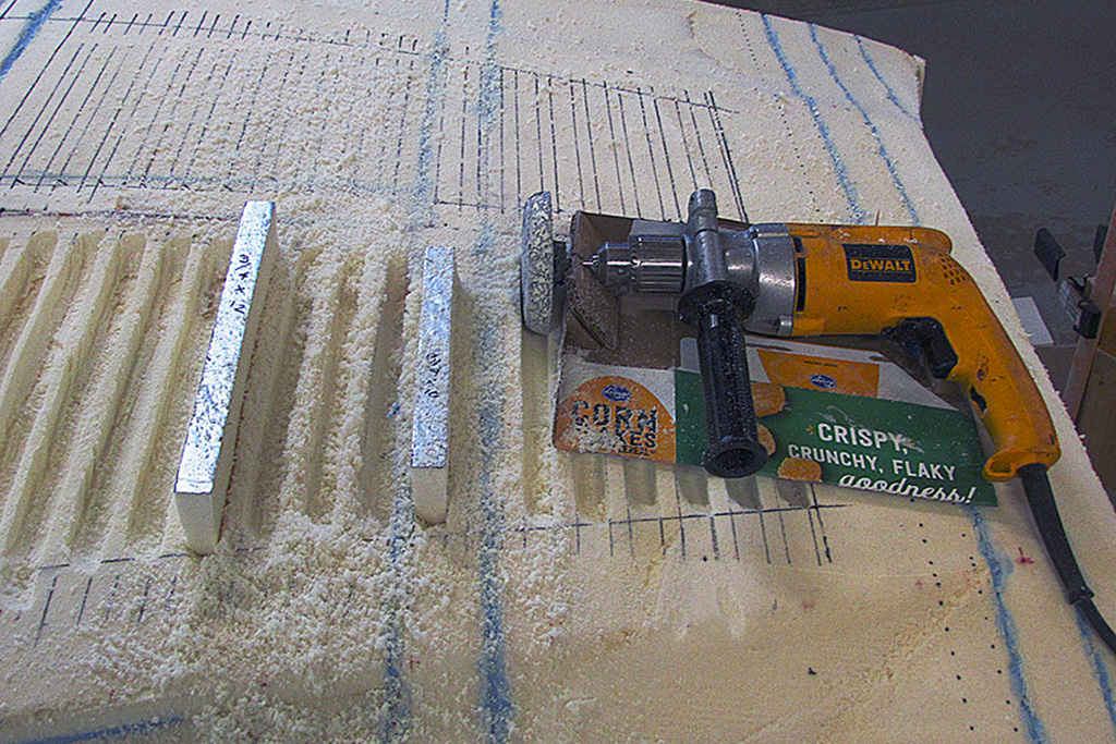
My second idea took a scuffing disc and shape it to the contour of the vent cross-section.
Then, to push or pull it thru the foam, I mounted the hand drill on a cardboard cradle.
I then pushed the scuffing disc along my marked lines.
One thing I had to do was cut and pull out the blue glue pieces.
While I was at it, I also cut along the marked lines hopefully to give a clean line when done.
Removing the glue saved the contour shape of the scuffing disc from being worn down by the rubbery glue.
APRIL
While all the above was happening, on the side I prepared drawings showing contours thru the windscreen and side glass around the cabin.
My thought is to closely follow the shape of the windscreen and extend it upward as a complete windshield.
The side close I hope to do the same and make it so it can crank up and down.
The difficulty is the changing rake of the windscreen as it flows from the front crease around to the doors and back to the rear deck.
The angle changes relative to the horizontal plane from almost 30 degrees at the front windscreen crease to nearly 50 degrees at the rear deck for the side glass.
Most of the change occurs where the windscreen bends around to the door front cut, and is nearly constant on either side of that bend.
Just this quarter I discovered a program to allow me to create cuts thru my surfaced 3D Monza SS file.
It is a freeware viewer from Solidworks called eDrawings.
I created several cuts of the cabin area from the front view and the side view and the top view.
I could then test what I would get if I extend the glass higher to where a top would be.
It looks good to do so, maintaining the same shape wraparound windscreen as the original car.
To have the side windows roll up and down requires a constant (unchanging) curvature side to side and up to down to be able to keep fitting the opening slit in the door for the glass.
If I can keep the same shape for the front windscreen, then I might be able to make it so I can swap out the taller windshield for the 5-inch high windscreen like on the original car.
That way I can have it both ways.
When shaping the windshield/side glass/top, I will duplicate the outlines on my chassis to confirm the final actual dimensions of this critical piece.
And if successful, I will had a removeable top that will stow up front.
Otherwise, I will have to go with the heavier fold-up convertible top with all the complication of stowage behind the seats and the extra weight.
Back to the Kamm tail. And to do that, it was back to the Kamm tail drawings as they located the tail light cones.
Using my concluded Kamm width of 43.5 inches, I confirmed the location of the cones, and the height of the cones based on my 3D plots.
With the cones in place, I needed to hard-surface them, since they wwere juat made of thick paper.
I used my epoxy gel from the gas tanks, but found it would smooth out but not even out the lumpiness of the semi-viscous gel/paste.
Rather than take the time to sand them smooth, and likely end up with something more oblong than round (I knew because I tried), I decided to cut them out and make new ones from sheet styrene, which I did.
That took another week.
While the new cones dried, I cut out a profile of the cabin top in 1/2 inch foam and placed it using my laser-leveling technique after leveling the chassis.
Then I climbed into the driver's seat and placed a level on my head and had my wife snap some photos.
Turns out my head is JUST under the top line of the roof, effectively even with it.
That was better than I feared, but still meant I needed to raise the roof, say, 3 inches for minimal operating clearance.
But before I design that, back to the Kamm.
The new cones looked good and sturdy and fit into the original openings.
Then came the setback.
MAY
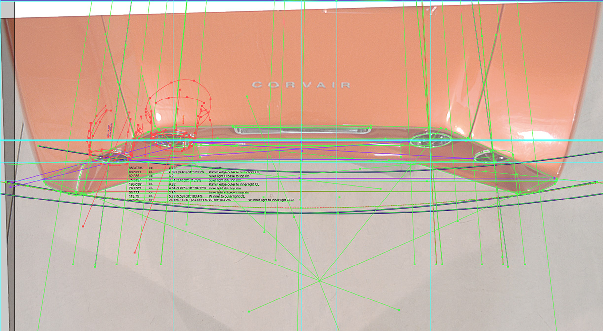
I like to doublecheck my measurements, so I consulted the one photo I had that showed the Kamm cove functionally as an othrographic look-down view.
I had earlier worked out the vanishing points, so I dropped the drawing onto my 3D Kamm drawing.
And lo and behold, it did not confirm the location of the taillights. . .
Well . . . it DID match them, but not the ones I was working with.
You see, I only plotted the driver half of the car.
So I then flipped that and aligned the two halves where I deduced the centerline should be.
But I also did plot all four of the taillights.
And when I flipped the halves, the left and right set of taillights did not overlay each other, i.e., they were offset from each other.
And the plotted photo taillights aligned not to the driver side lights, but to the passenger side lights, which wanted to be farther apart.
I refined the photo vanishing point, which changed little, but confirmed what the photo showed me.
I tried to scale the width to the width of the license plate bezel, but kept getting a wider Kamm than I could justify with the published width of the car.
What to do?!?!
Well, . . . in any case, it meant that the distance between the inner taillights was too narrow.
They had to be wider apart.
And that meant I had to make the Kamm wider.
And THAT meant I had to CUT APART the Kamm cove and add a big spacer of about 1-1/2 inch!!
So, I did.
Time to take a short vacation. Which I really did.
SIDEBAR: The BEST Foam Glue Is . . .
When I began the body fabrication, I decided to build it up from panels of 2" foam.
But how to glue them together?
My first method was to use contact glue on the still-foil & plastic-coated cut sections.
This quickly proved a mistake.
It held okay, but sanding or rasping over the glued coatings resisted the rasp and left a raised edge that had to be dug out.
My 2nd method was to use Gorilla Glue.
This was a workable solution, but not an ideal one.
It was drippey and messy to work with, and had to be clamped together because it expands as it hardens.
Also, it grips well, but the foam is granular and allows the hardened glue to be pulled away from the foam, i.e., it detaches with light effort.
And, it still produces a slight raised edge when rasping due to the glue being harder than the foam.
My 3rd method was to use construction-quality white glue that I bought by the gallon at the orange-box store.
It did not hold quite as well as Gorilla Glue, but did sand and rasp more easily without being noticeable.
But, I gave up on it when I discovered that if it did not get exposure to air, it did not dry.
Even clamping it did not do the trick.
There were pieces that after two weeks were still wet and fell apart.
So Gorilla Glue was the best option I knew.
Then one day . . . I had an epiphany.
Use foam to glue foam together.
I had worked with gap-filler spray foam.
It, too, was an isocyanurate like the insulation foam.
And it was pretty sticky stuff!.
I knew that it had to be exposed to air to cure, after working with the gas tanks.
So I test-glued two scrap pieces together and clamped them tight.
Within two hours I had my answer.
They bonded much more strongly than I expected, needing no reinforcement.
The two became one, and were effectively one piece.
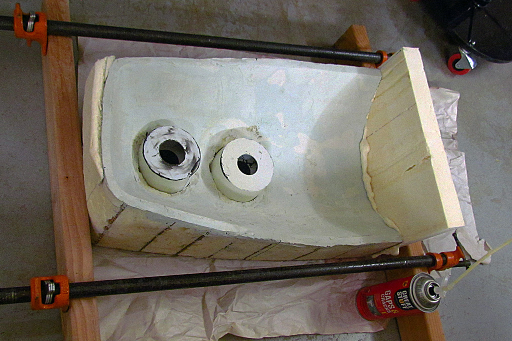
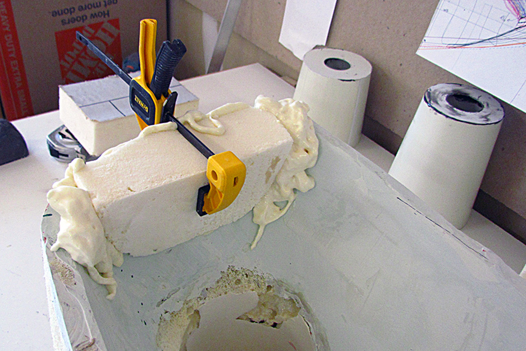
The proof came when I glued the filler piece between the two halves of the Kamm cove.
No reinforcement was needed!
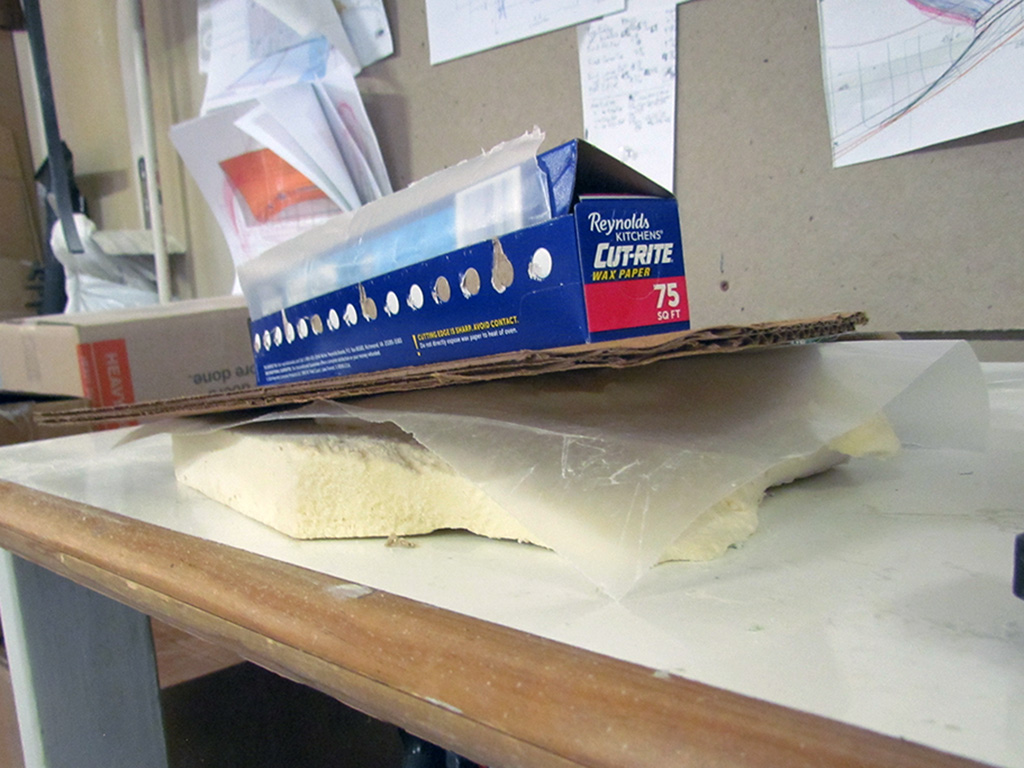
Back again and back into the garage. I tested working with spray insulation foam and sort of shaping it by covering it with wax paper and placing a weight over it.
Yah, it sort of worked, but the center area where I made an indentation stayed liquid until I removed the waxed paper.
More testing needed.
The Kamm cove shaping continues by adding foam to the outside edges to bring them to the 43.5 inch width I settled on.
I was also able to shape it into the cove toward the outer taillight opening.
While the foam and Bondo dries, I began mocking up the removable top I hope to use in lieu of a convertible top.
I start with 1/2 inch foam and make a centerline profile.
I cut out an opening shape of the cabin from thick corrugated box cardboard.
The piece with the hole went on the chassis and is positioned to correspond to its placement on the car.
I then positioned the centerline profile and carefully climbed into the driver's seat and checked my head height against the profile with a level.
My head would rub the roof, so I add three inches to the profile and try again.
Yup, it looks like for sure I will have between 2 to 3 inches of head clearance.
Good enough.
I cut another foam profile to set on the foam body and begin cutting and foam-gluing upright panels to it to represent the windscreen and side windows.
Next step is to determine how to mate the two, differently-angled surfaces (windscree to side glass).
JUNE
Let's begin the month reviewing how we got here.
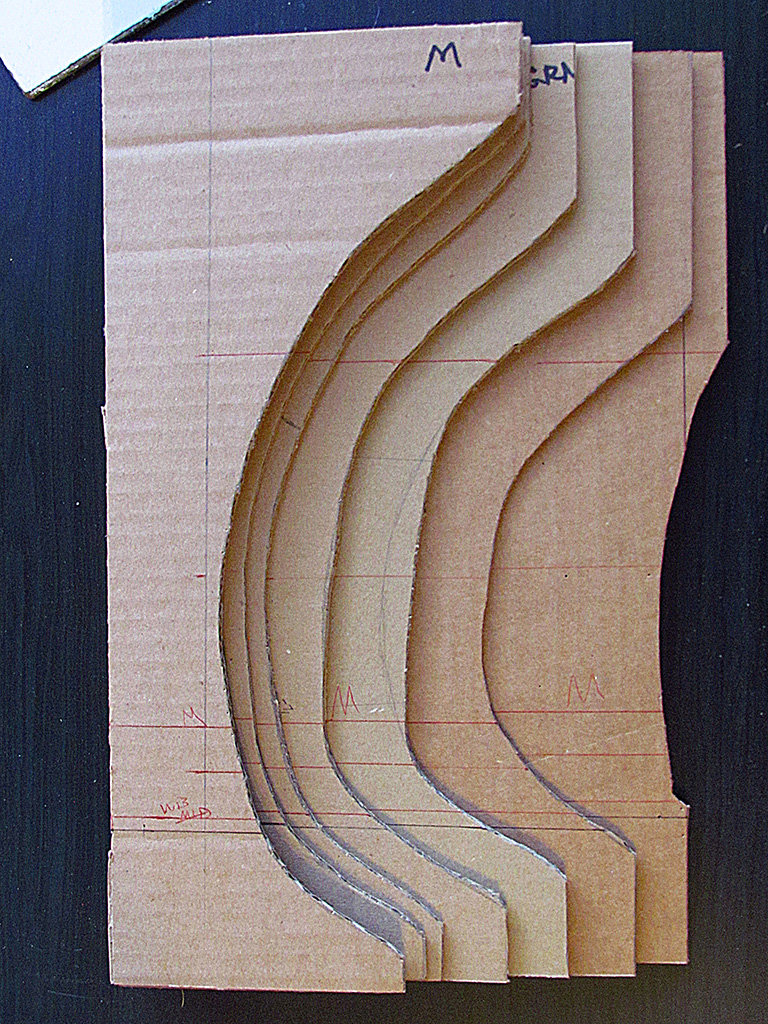
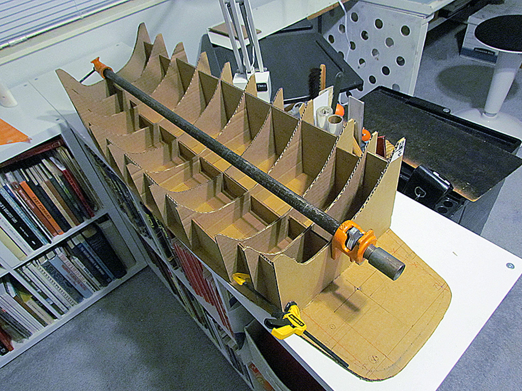
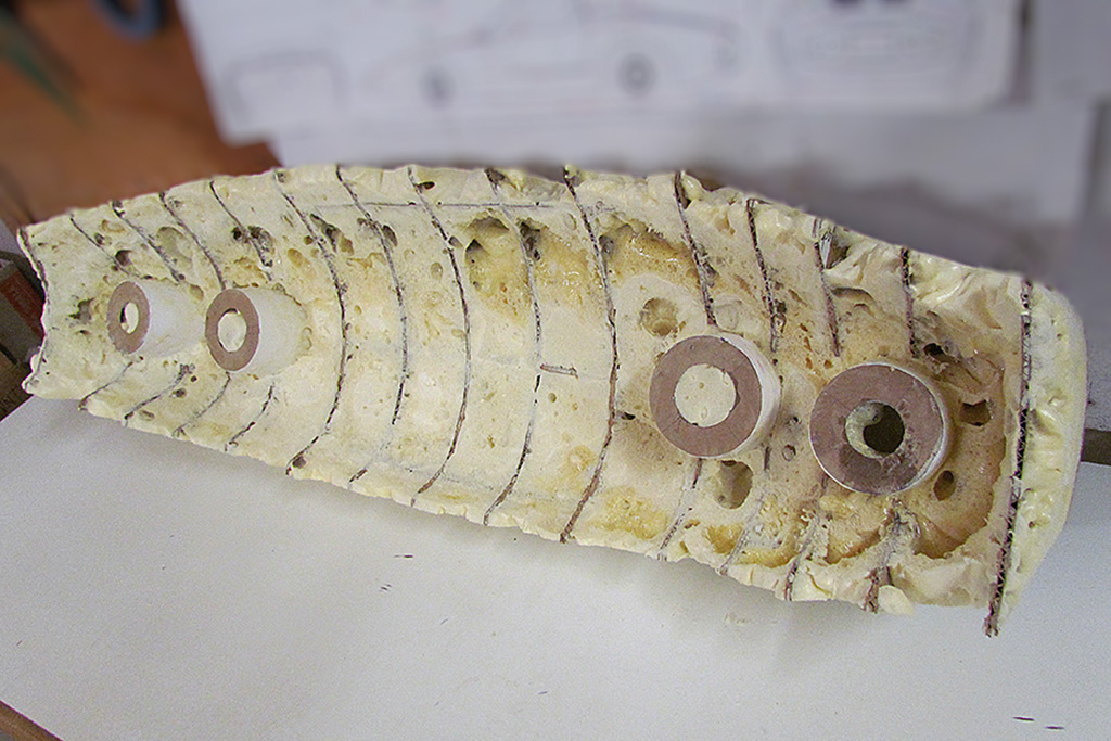
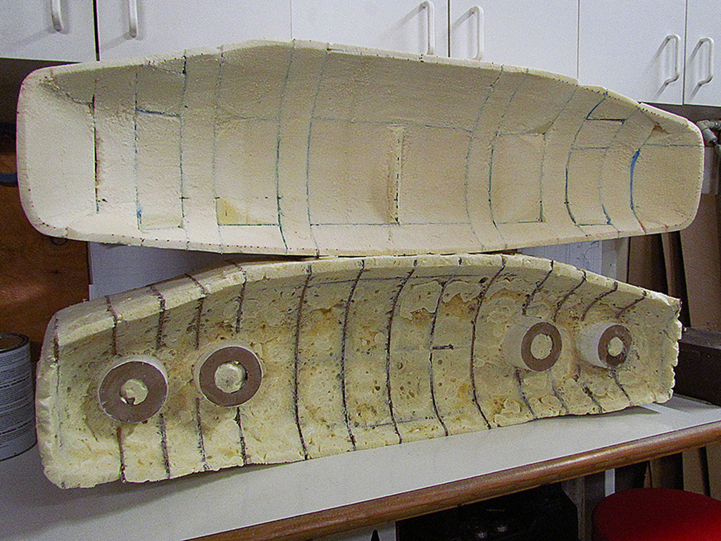
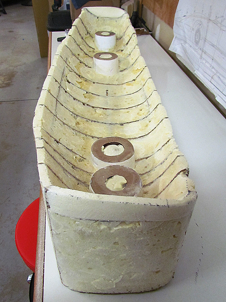
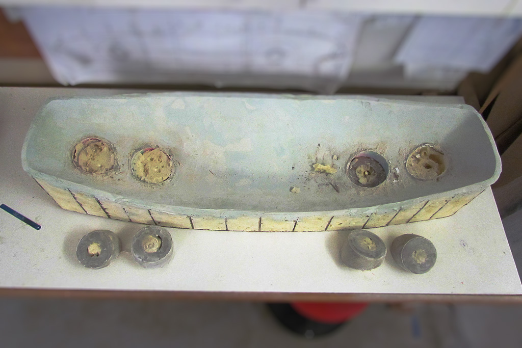
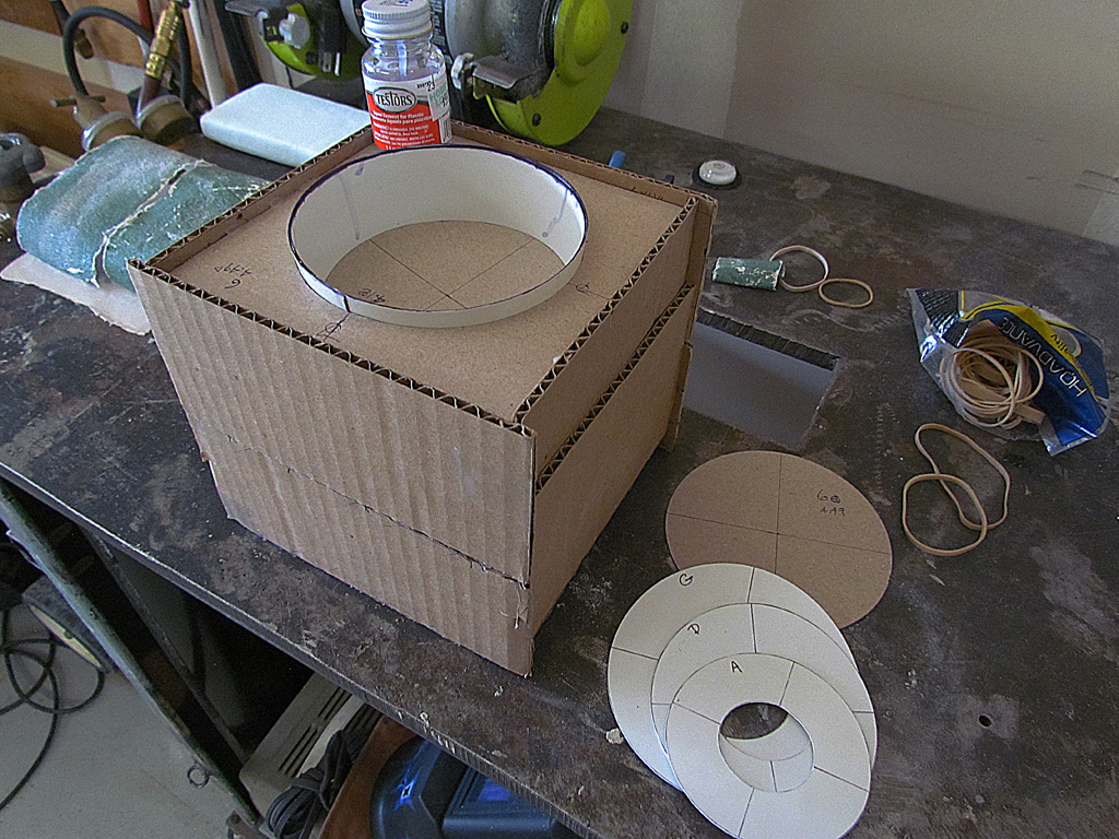
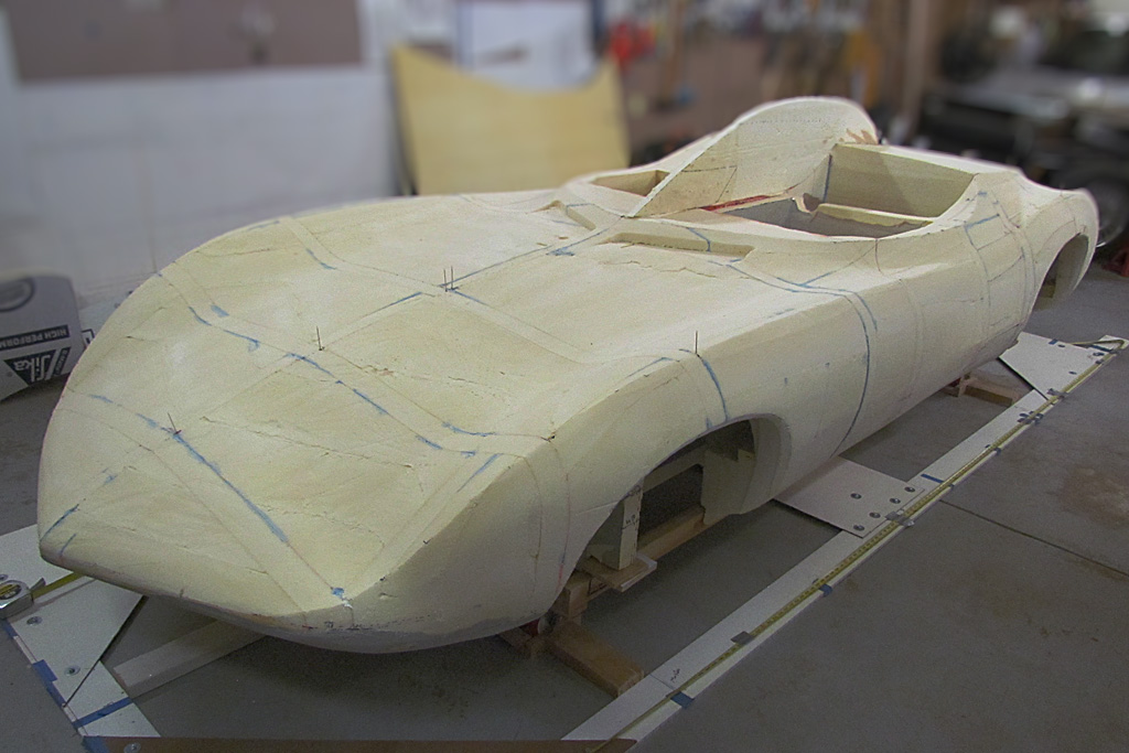
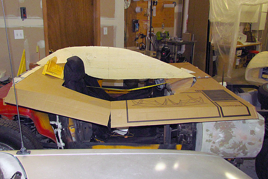
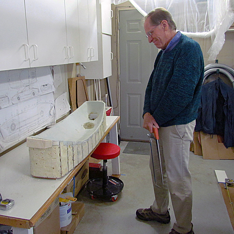
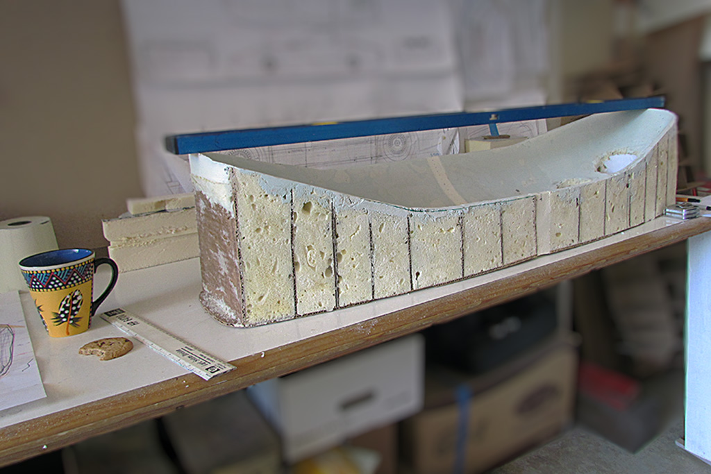
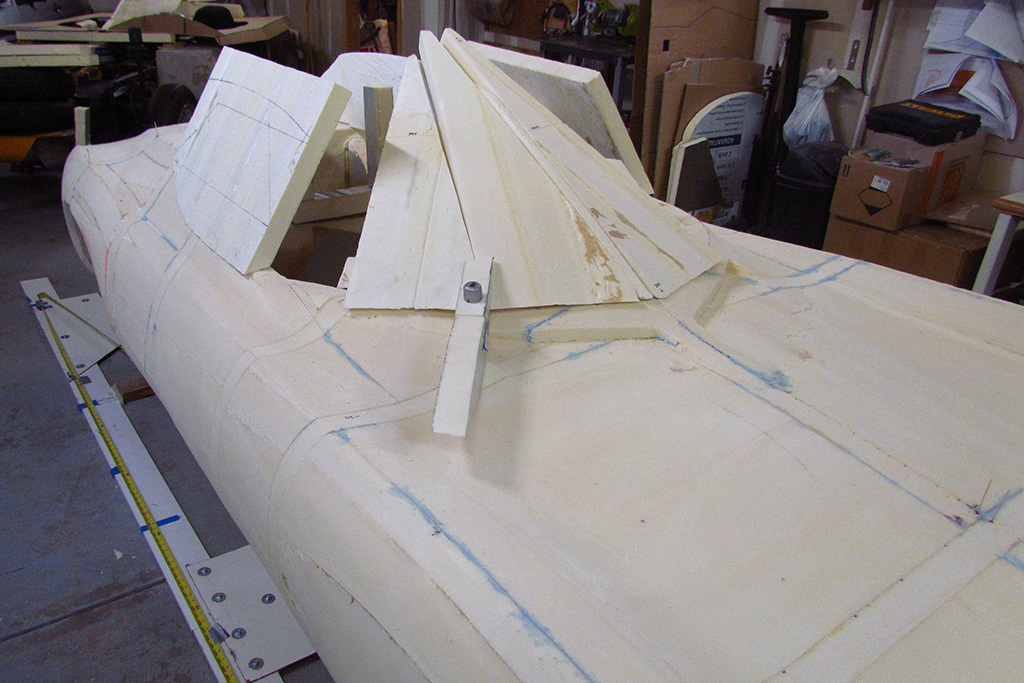
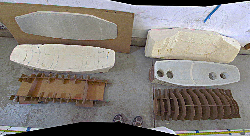
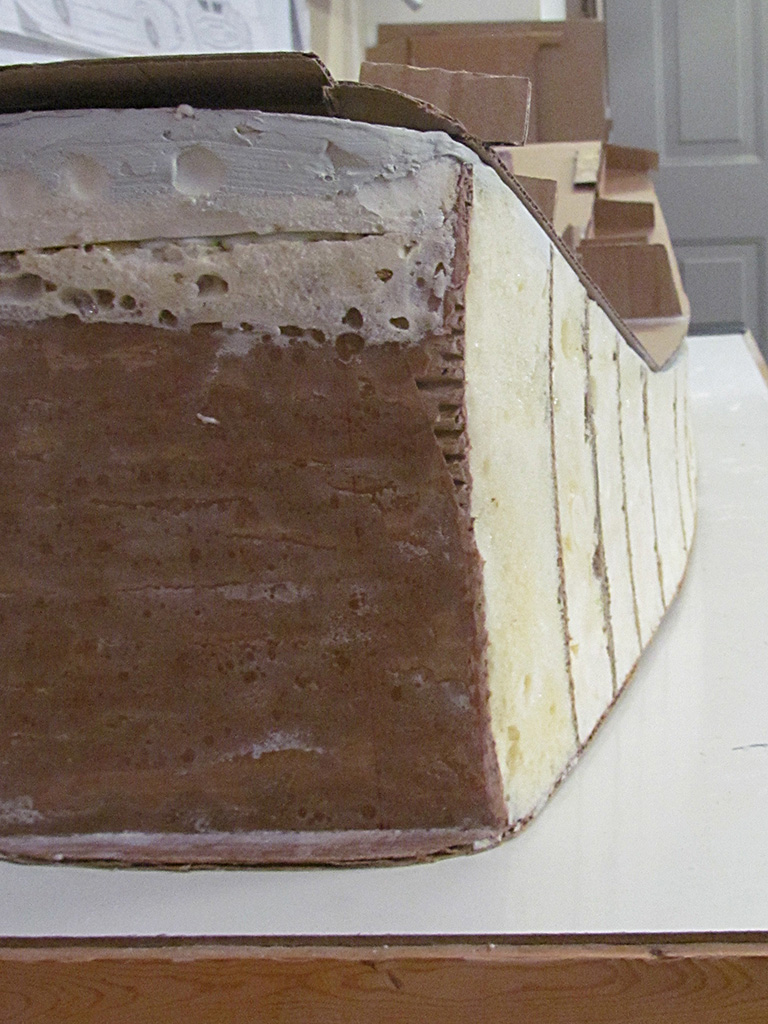
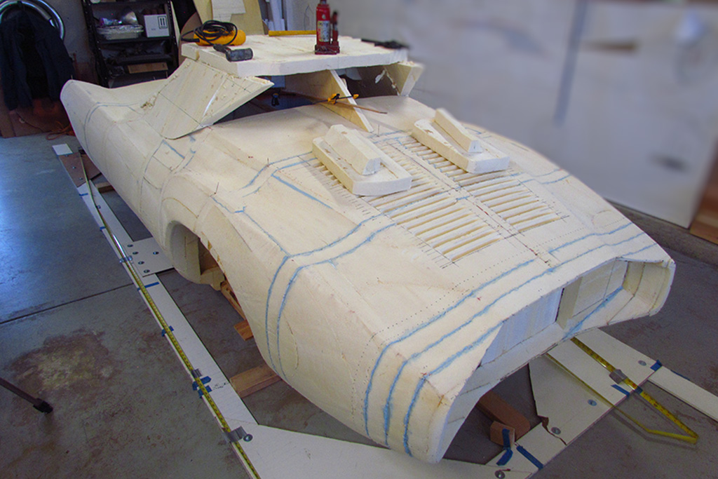
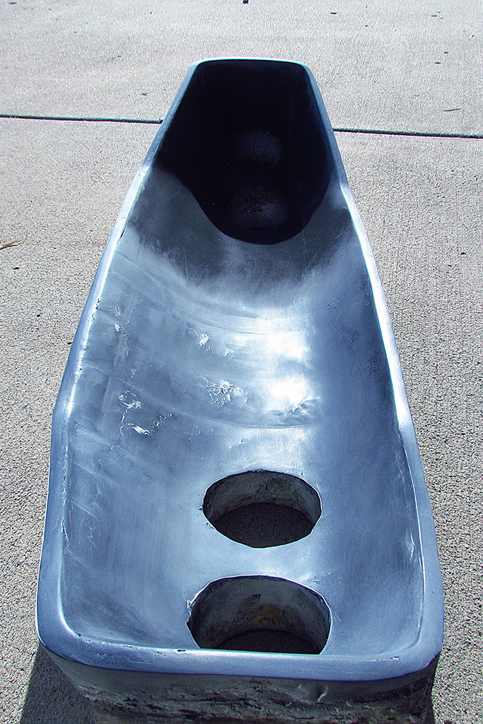
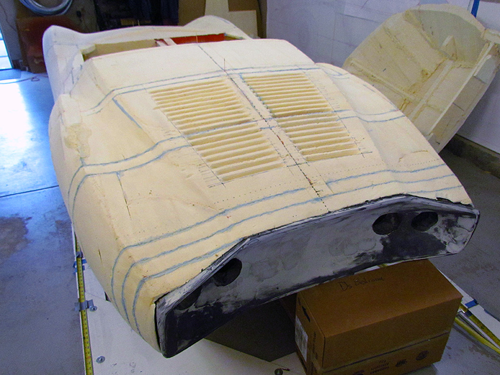
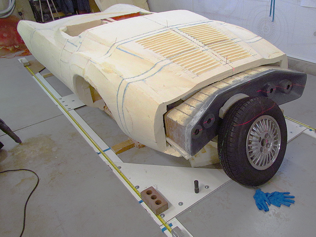
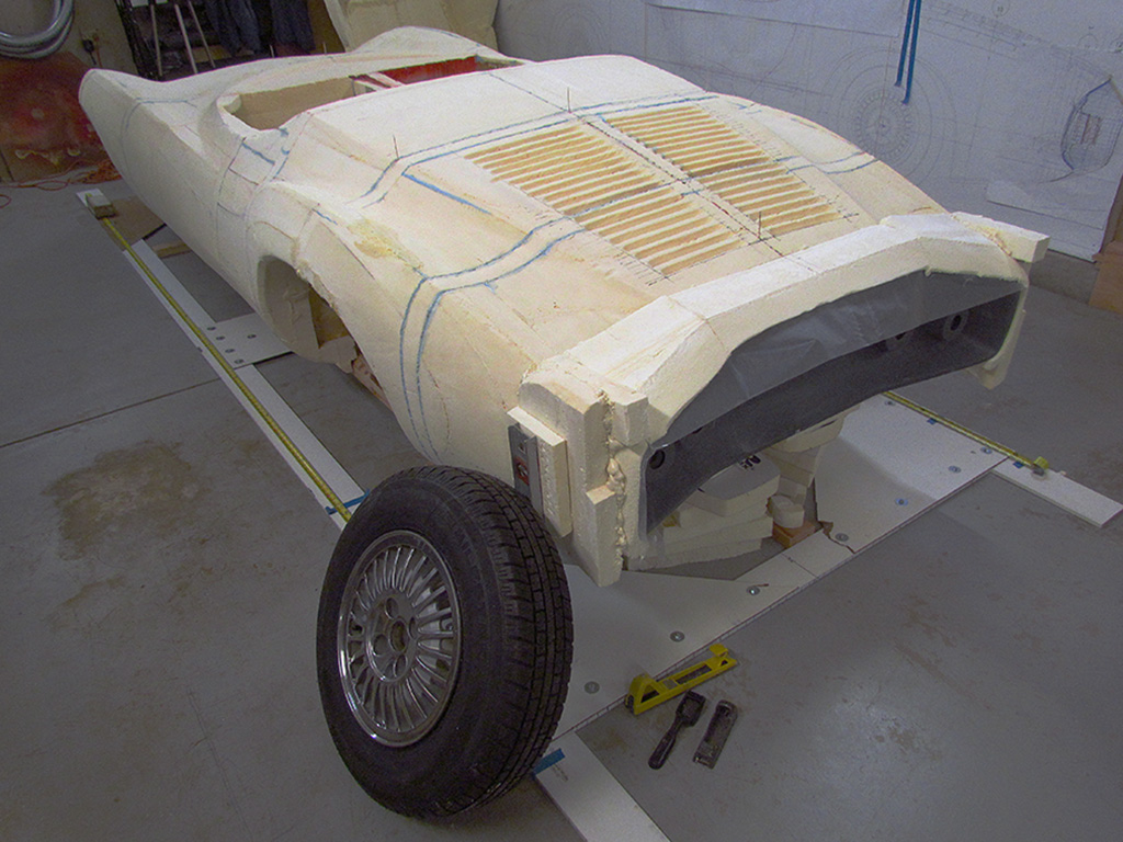
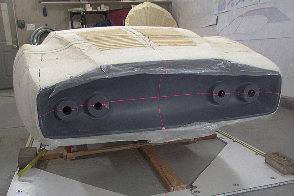
The first June pix shows the different attempts I have gone thru making the Kamm cove.
There are four foam versions and three major cardboard patterns I made trying to get this to look close to the actual tail cove.
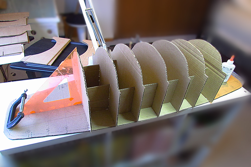
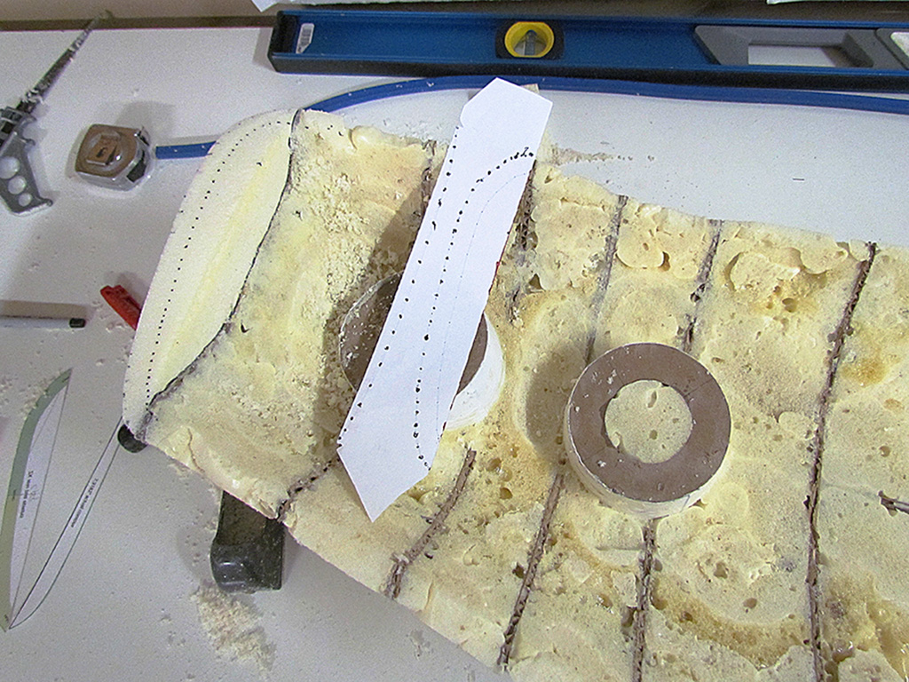
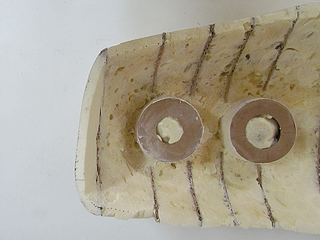
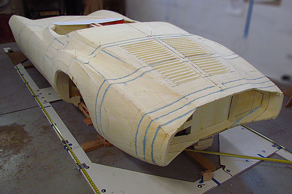
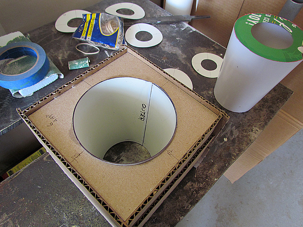
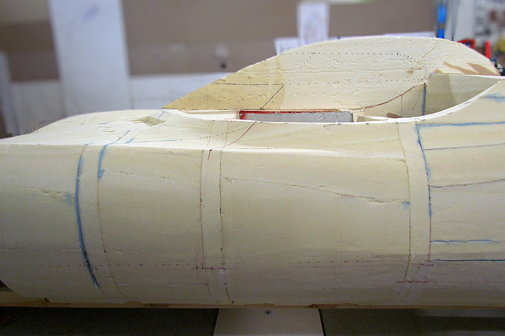
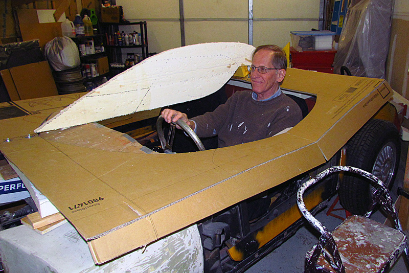
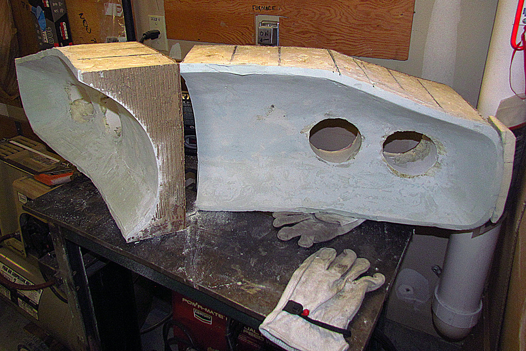
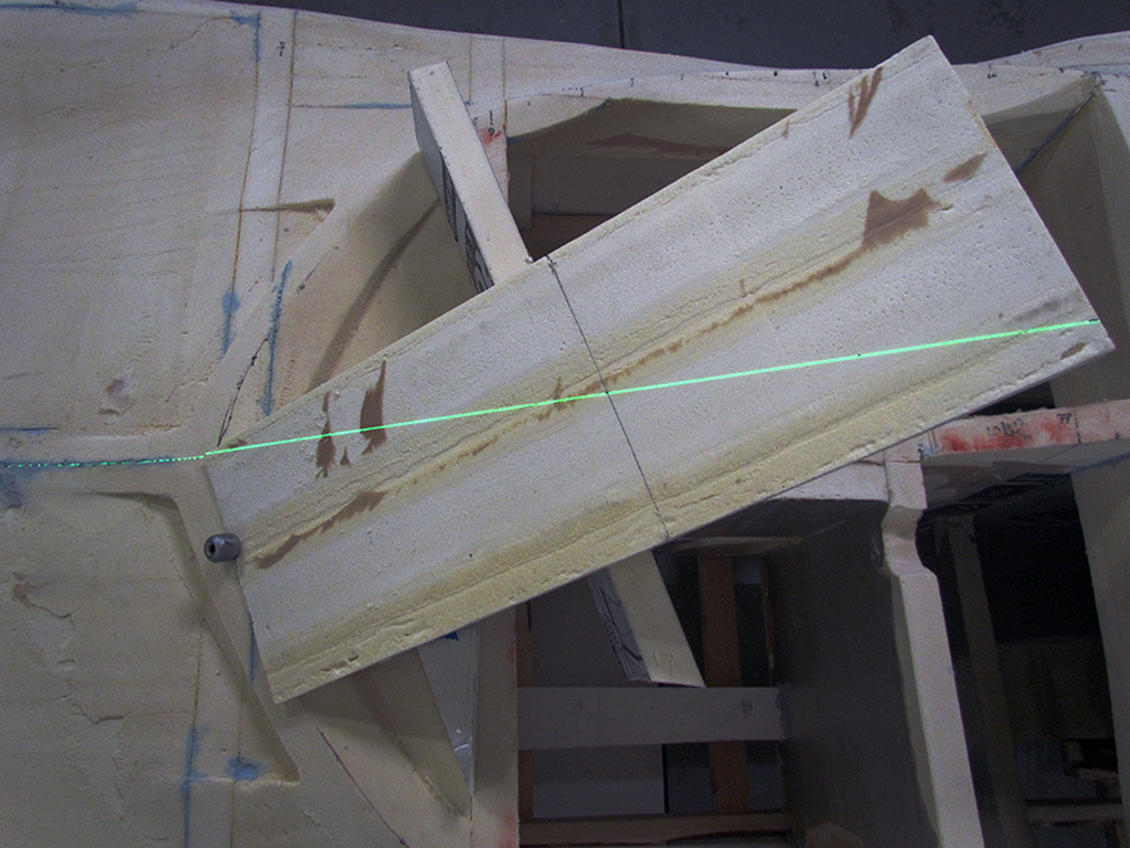
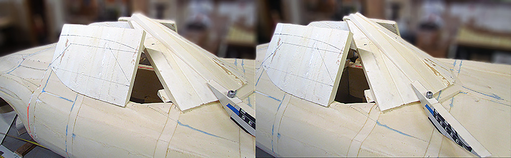
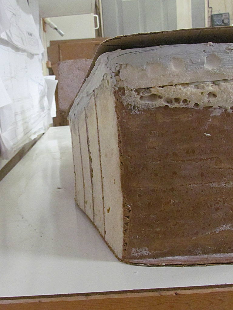
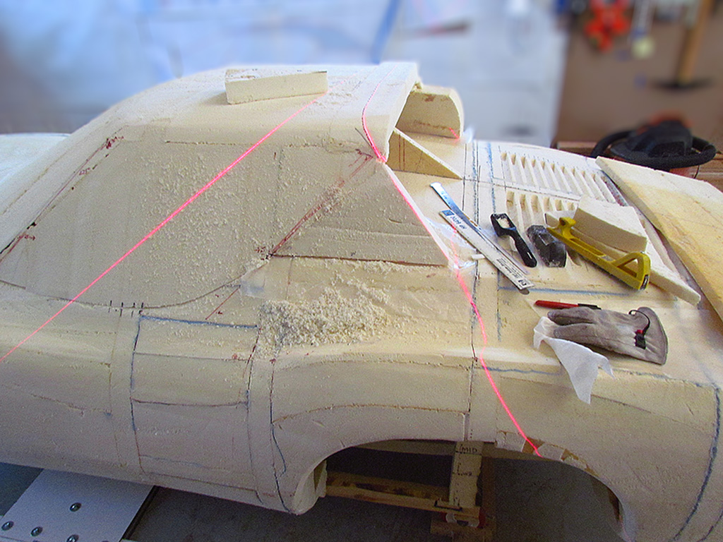
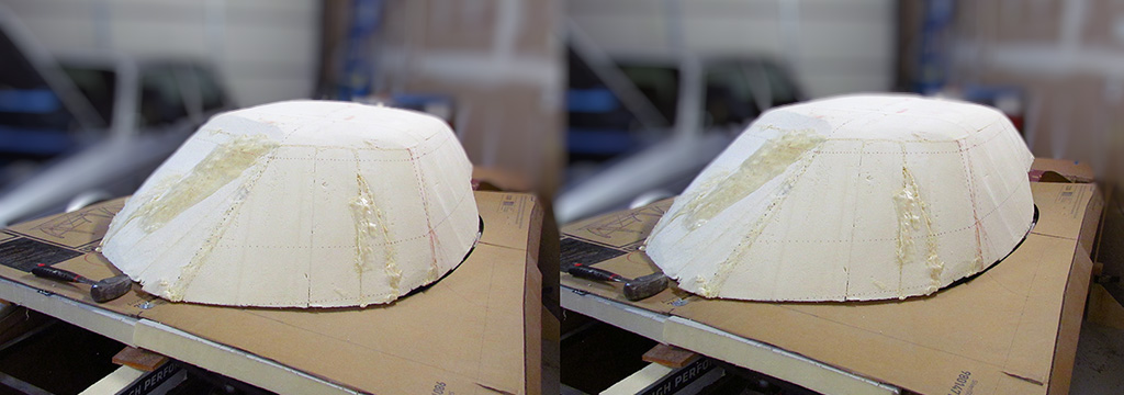
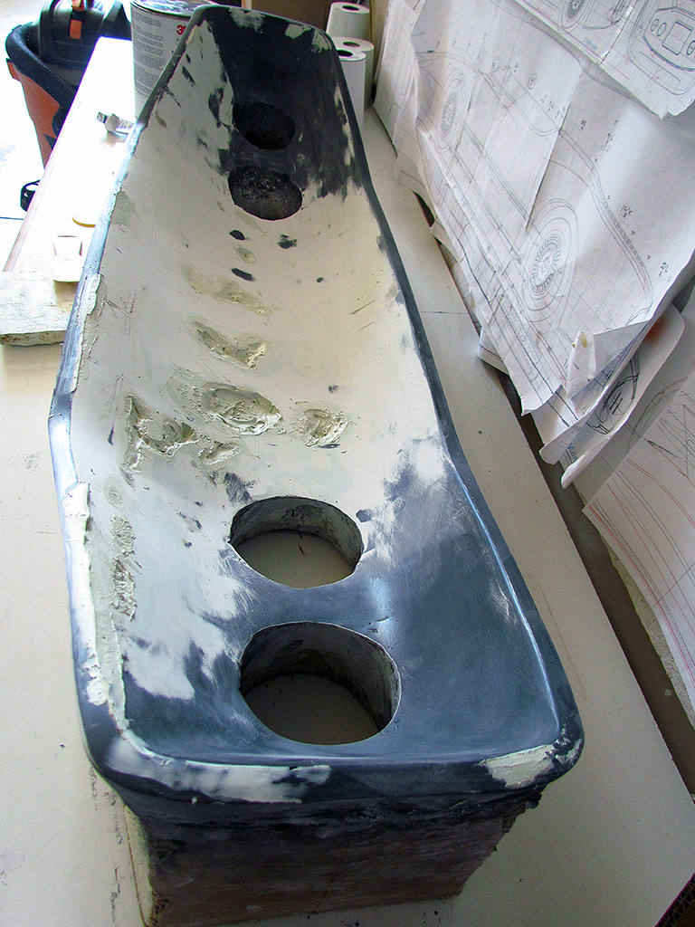
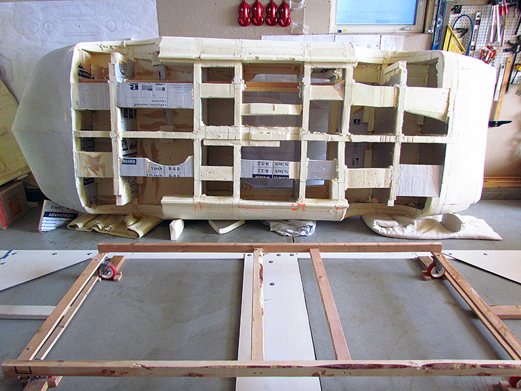
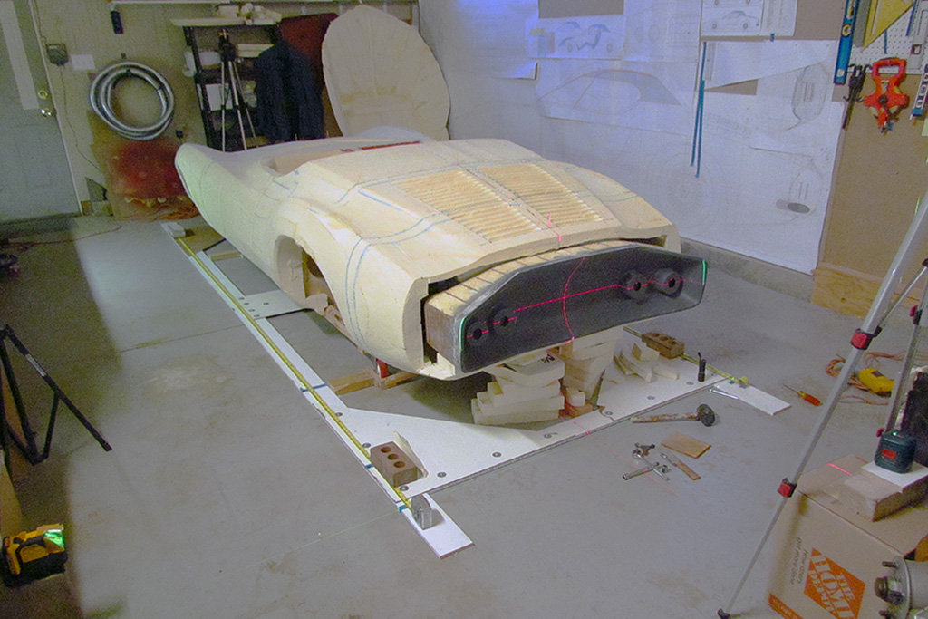
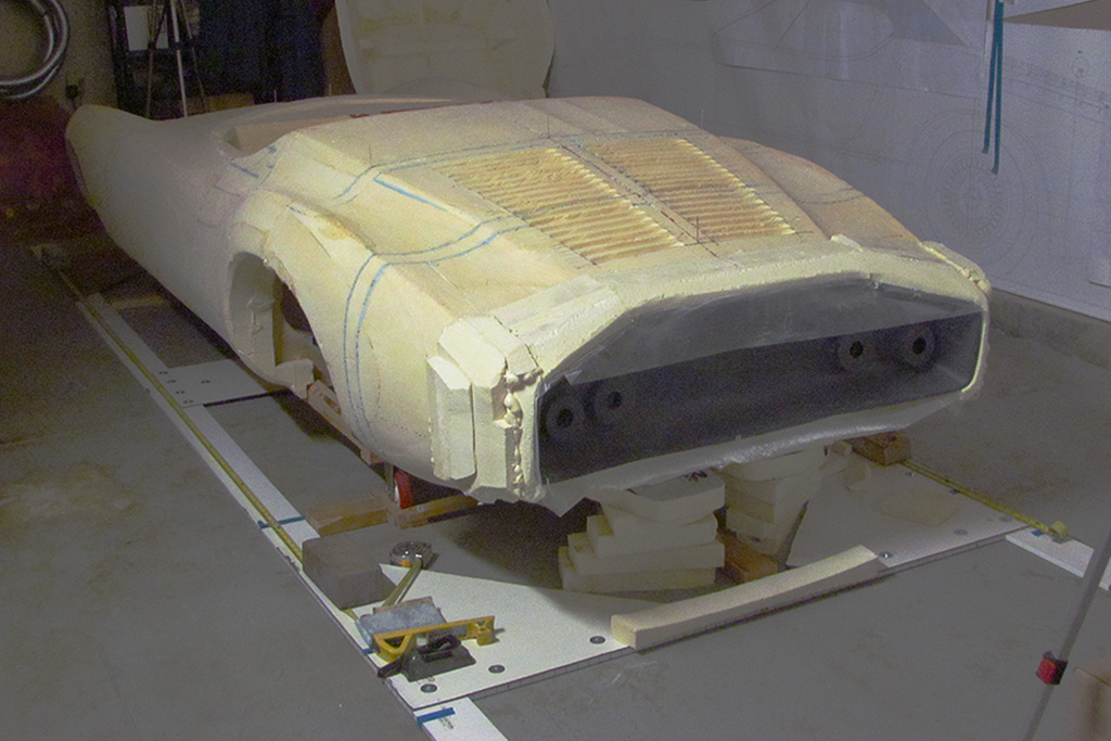
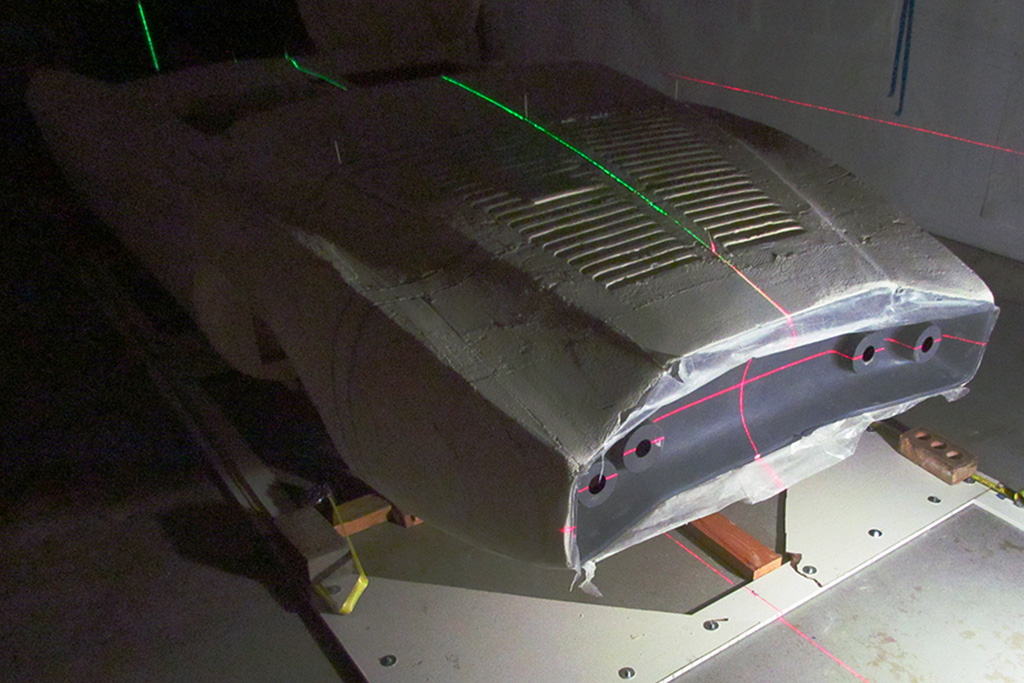
The third pattern is shown in use in the 2nd pix.
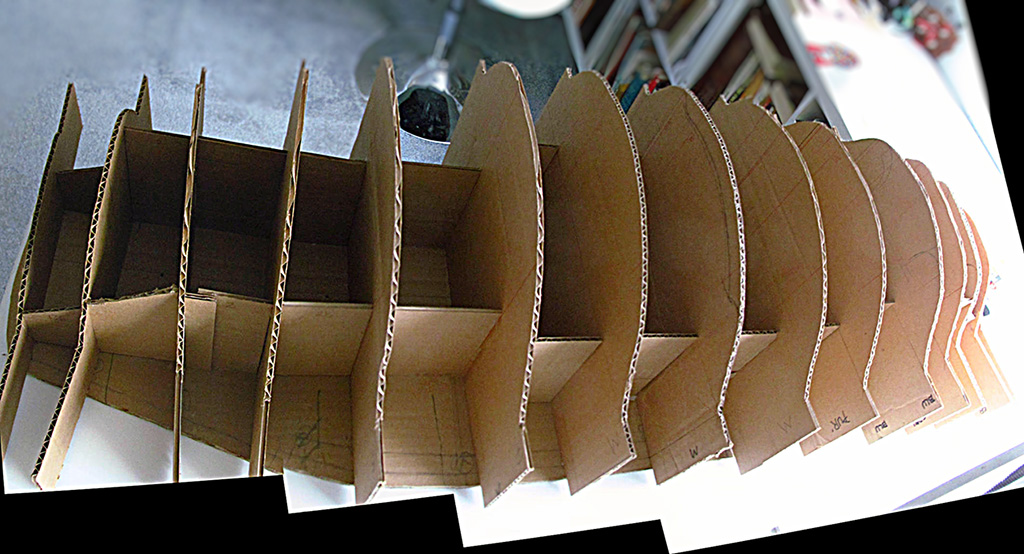
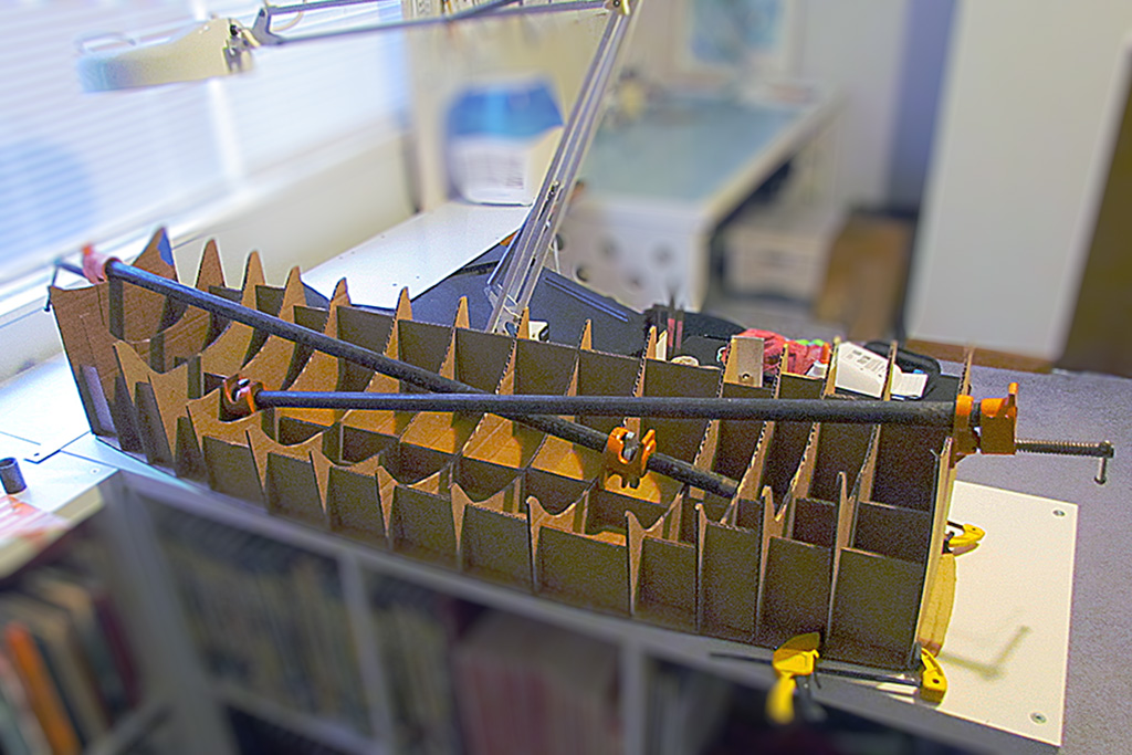
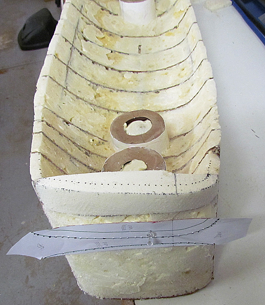
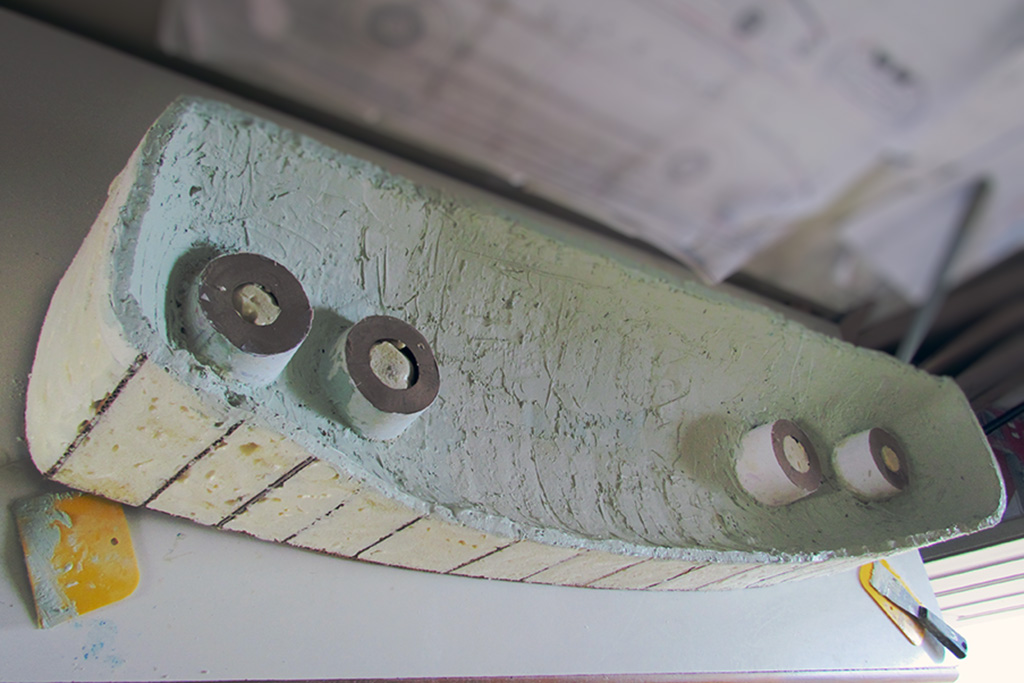
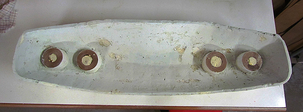
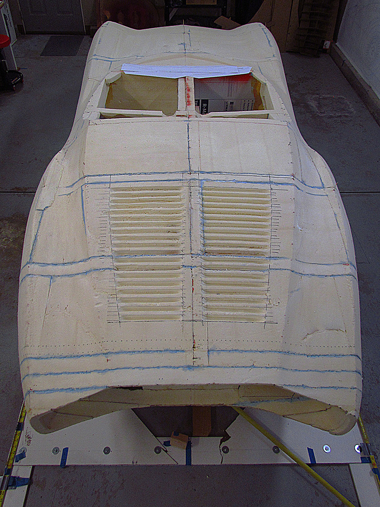
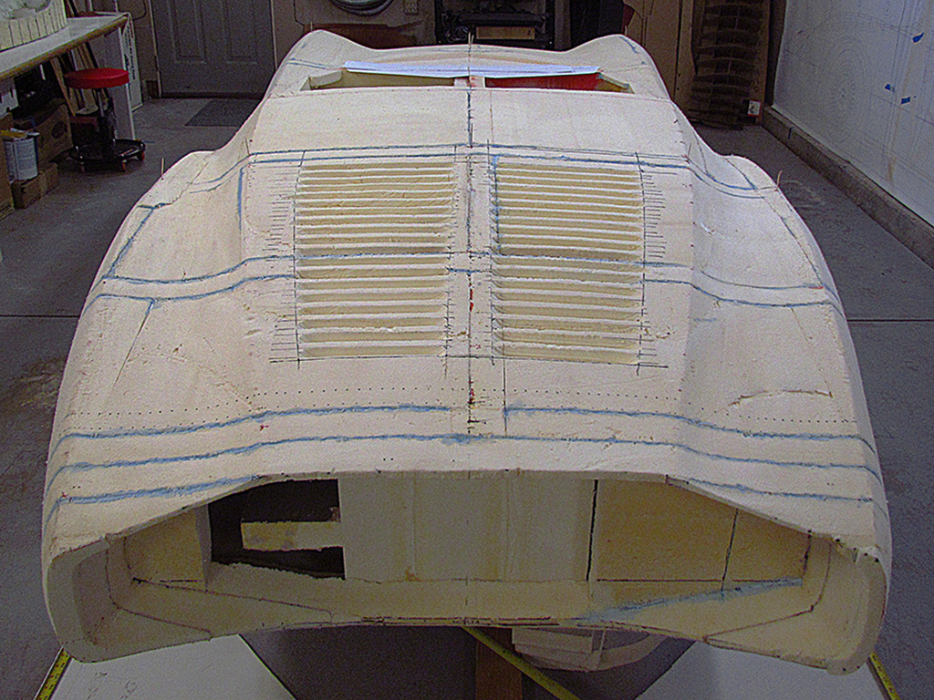
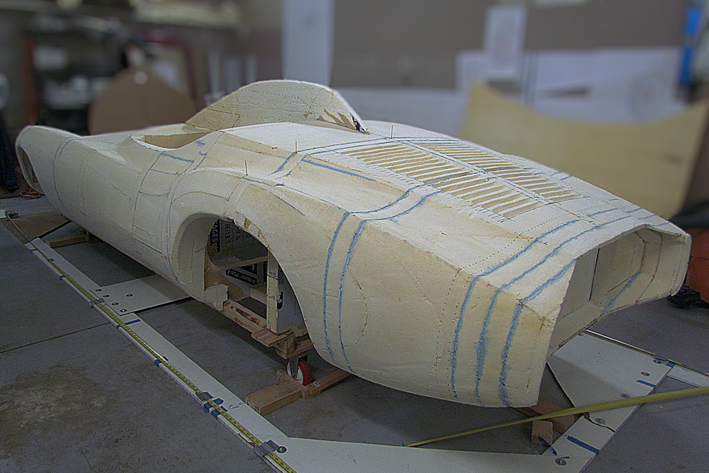
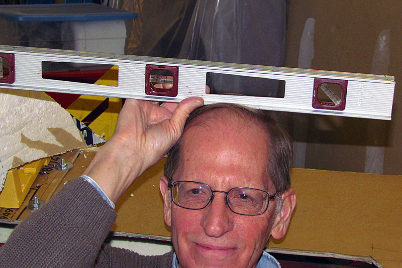
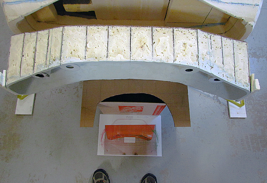
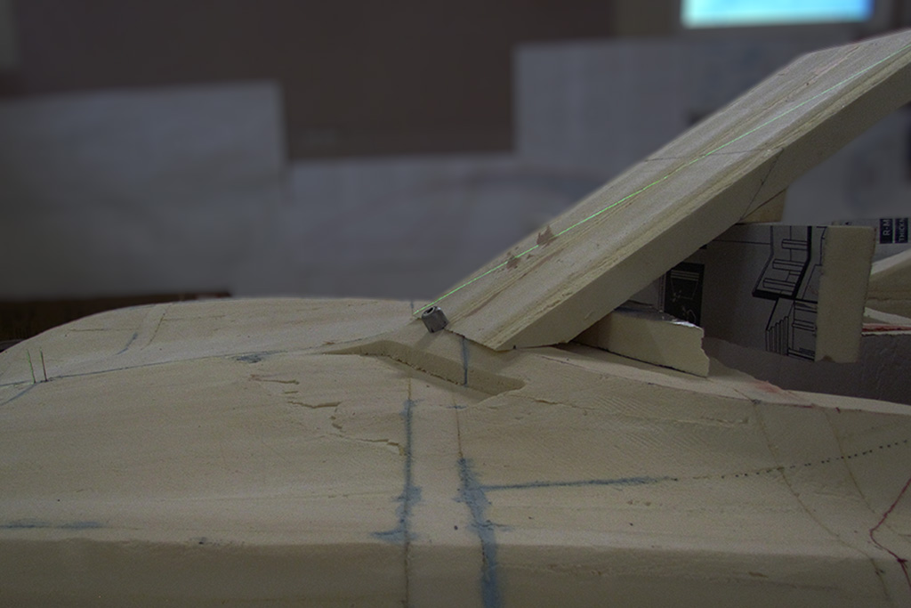
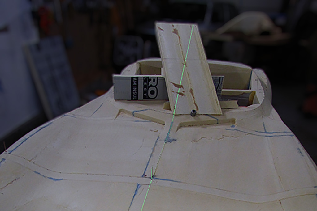
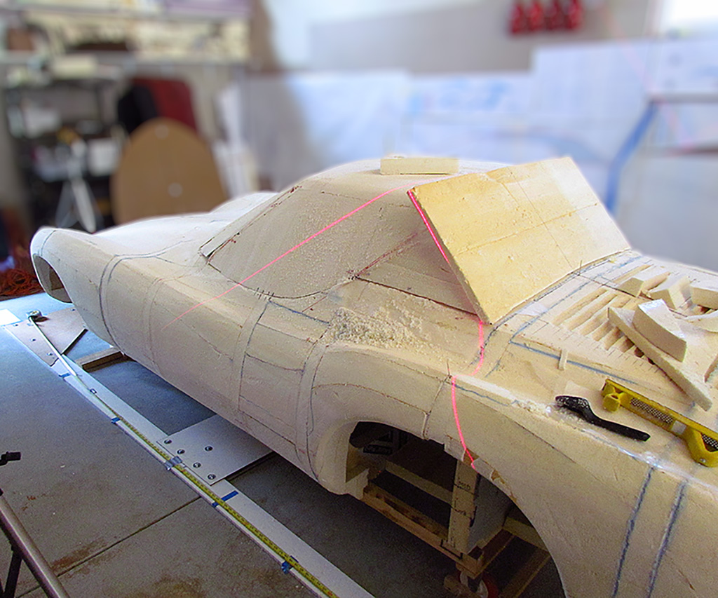
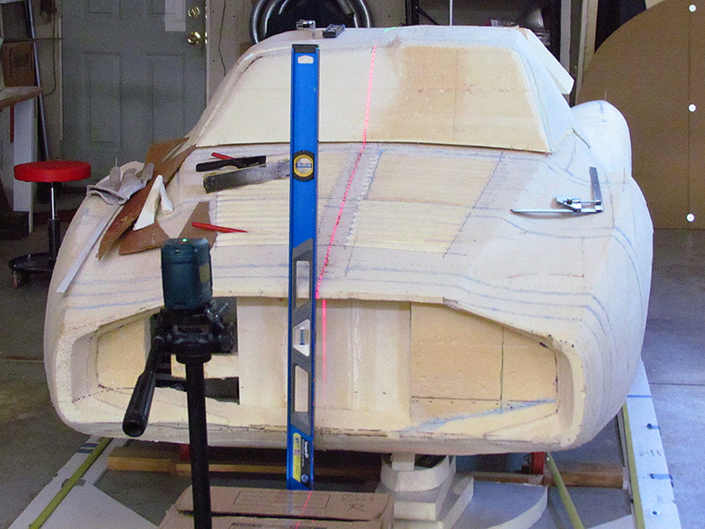
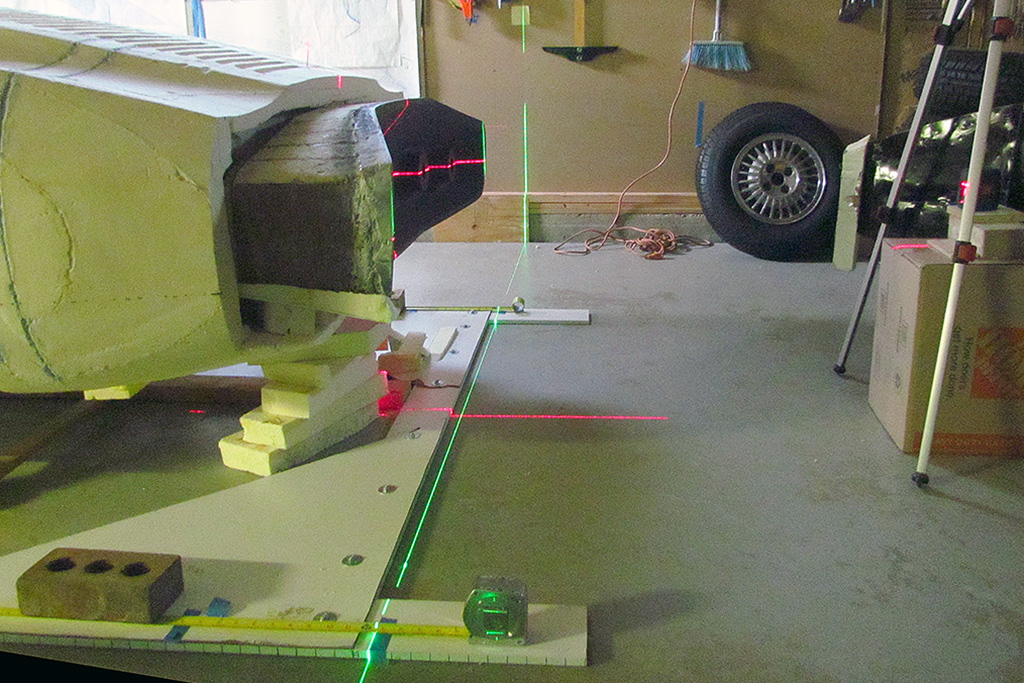
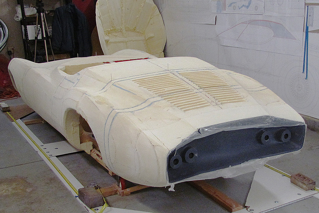
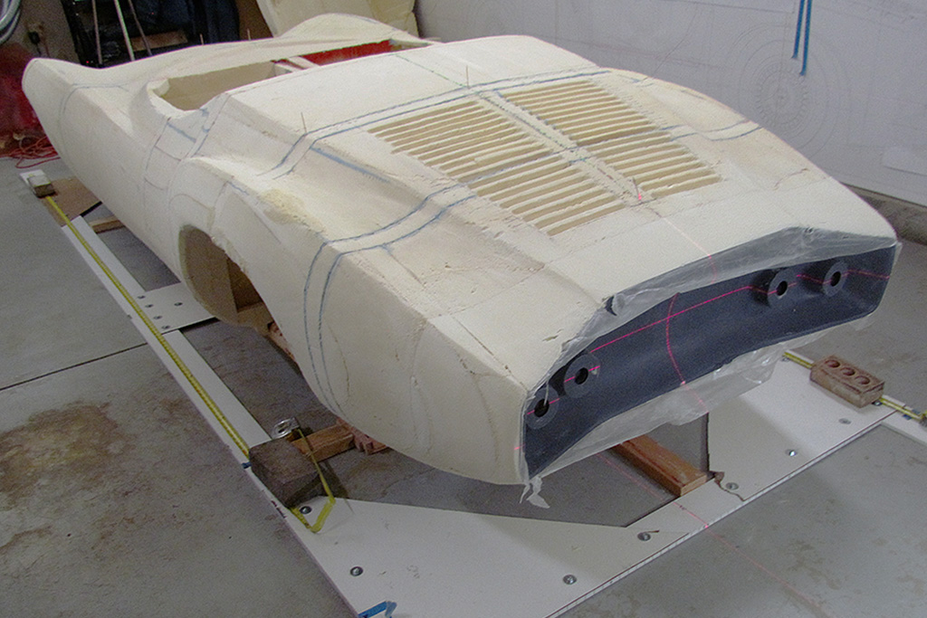
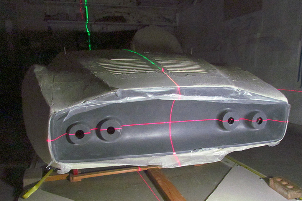
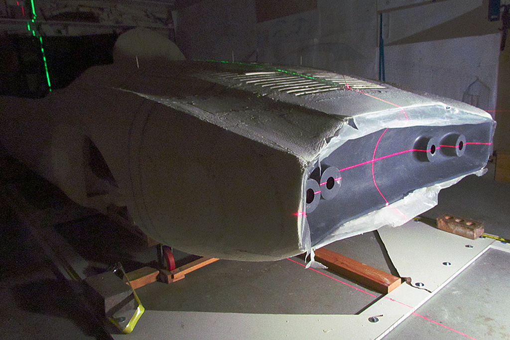
Aligning it is a study in best-fit, as the 3rd and 4th images show looking along the top and bottom edges.
I continue throughout the month repeatedly checking the cove outside rim and adding Bondo repeatedly to repeatedly build it up to eventually sand it to shape.
Waxed paper works great to make a flat, smooth surface.
Just pull it off when the Bondo is firm but before it hardens.
During drying times, I continue adjusting the window panels to determine how to achieve the final shape.
The side windows must go up/down about 10 inches, but not all the way down. I intend them to stop at 5 inches of height to match the real car's side glazing.
It is a straight-line section up and down but curved slightly front to back.
Note that they must go up and down and when seen from the side, they are cut to a rake of 45 degrees, which on the rear rake will extend into the B-pillar when raised.
And by quite a bit.
The problem is merging the 25-degrees-from-horizontal of the windshield to the 62-ish-degrees-from-horizontal of the side windows with their 45-degree angle.
But after much measuring and plotting, I think it will work and the hard top will detach and fit into the front trunk.
Continuing with the Kamm cove.
I realized I needed to focus on tightly defining the lip, or edge, of the cove.
Little by little, the rear-view outline was established by slowly building up all arond - especially at the major bends.
Then, I could focus on building up the edge to the correct depth (front-to-back, center to outside wings).
It took multiple sessions adding and shaping Bondo applications.
When THAT was established correctly, THEN I could shape the edge into the cove area.
I did a rough sanding on the top edge transition, got tired of working on it, and moved back to working on the top.
JULY
Building up the top was a truly step-by-step, trial-and-error process.
I had my side profile determined and had started with the windshield at an aggressive rake of about 27 degrees.
That was greater than the +/-22 degree rake of the original 5-inch high windscreen.
The side windows were positioned but needed to be shaped for curvature and especially to blend into the windshield.
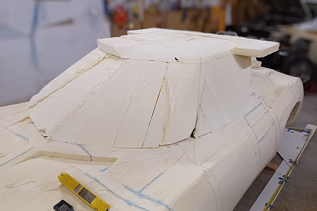
Then the roof was added and roughly shaped; then the B-pillars; and finally the rear window surface.
Along the way I had some fun with it when I place a remainder cut-out piece of foam at the back of the roof.
It sure looked like something Syd Mead might do on one of his USSteel rendering, or that Ed Roth might toss in.
It was very 1950s, rocket-to-the-future looking.
But then I began to think now it might be very practical . . .
The two wing extensions on the side could be used contain Cibie headlights on the front, and extra safety taillights on the back ! ! !
Naaawwwhh - That would be TOO wild.
By the last week and after much shaping on the driver's side, the basic roof shape was good enough to test . . . Would it be tall enough on the chassis?!?!
And the answer is ------
YES! With an inch or two to spare.
BUT . . .
The windshield rake prevents the steering wheel from flipping up more than a notch past the vertical position.
I think I will have to go with a swing-away like on the '61-'63 T-birds. Or else a removeable wheel.
AUGUST
The Kamm cove just does not want to be finished. It was primed and I thought it was ready to add the taillight cones when I caused a big problem.
I placed it in the sun for an hour to thoroughly dry the primer.
When I came back, there were cracks in the surface and the foam had expanded between the ribs.
I gouged out those all enough to add new Bondo and started sanding it all again.
I had to build up the rim in places and correct the overall outline and rim heights.
And still, imperfections kept appearing, requiring touchups.
Very frustrating.
While Bondo was setting, I worked on the poptop, continually shaping it.
The window surfaces were most important to establish, especially where the windshield meets the side window, and what slanted angle the side window would take.
Since the side window will roll up/down, it will need to be the same angle front and rear.
(quick aside - It does not HAVE to, but in order to avoid an open gap between windshield and window, it will have to go up as the same angle as the windshield A-pillar. And the same issue occurs at the B-pillar.)
But how much of a rake could I give it and still have a nice profile on the B-pillar?
Remember, the windshield at the A-pillar has quite a rake to it in side view.
I got it close to 60 degrees from vertical.
Then I reshaped the roof and did a rough match on the driver side before removing the top from the body.
While more Bondo sets, I decided to get the chassis going.
The engine had not been run in two years.
I first needed to replace the starter.
That turned out to be a simple job.
Next I suspected the fuel pump was not doing its job.
I checked in with the local VW mechanics and learned I could test it simply by pushing open the flap valve on the MAF.
It worked! And so did the engine. This takes me into...
September
... But that revealed another pesky problem - an oil leak around the #3 pushrod tube. White smoke galore as it dripped onto the exhaust pipe.
So I pulled it and added RTV to the seals and tried again.
Smoke galore again.
So I pulled it and cleaned off the RTV and replaced it with the last of my seals and simply oiled them and reinstalled the tube.
I also checked behind the rocker arm cover on the other side, and discovered the washer for a rocker arm lock-down bolt had broken in half and left the rocker arm out of adjustment.
I fixed that, then started up again.
Well, first of all it ran rough, and then there was a LOUD metallic POP, and it ran well!
I decided the push rod was slightly misaligned and had corrected itself. It ran well, so let barking dogs bay!
More Bondo. Time to adjust the shift linkage to be able to get it into gear.
By now, I am into...
October
... and I can only get 2nd and reverse to work - and reverse only works when I put it into the 4th position! Something is very wrong.
The best guess is two-fold: the T4 shifter has limited reach compared to a T1 shifter (this IS after all a T1 transmission), and/or...
After talking with the builder of the transmission, who has done hundreds (yes, hundreds) of these transmissions, there must be something wrong with the shifter/shifting geometry.
How else to explain that it is engaging reverse in the opposite position than it should be?
That has to set a bit. The body takes precedence.
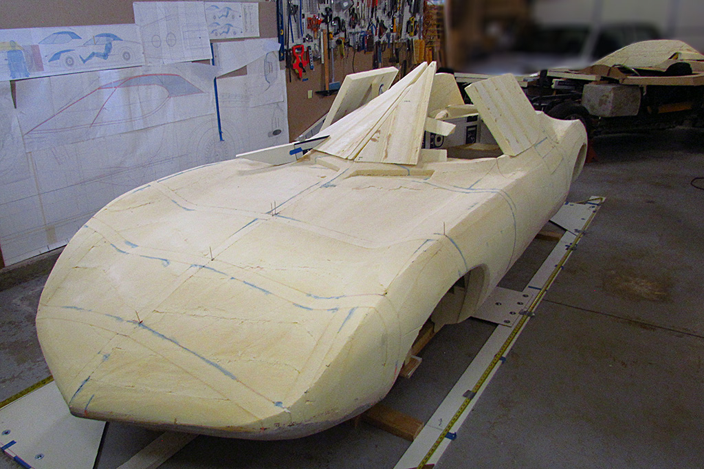
With the cove nearing completion, I need to address reinforcing the body with an internal frame.
With the help of wonderful neighbors, we lift the body off the base and place it on its side, exposing the underside.
I begin to cut holes to run two lengths of 2x3s, placing them at the level of the waistline.
Actually, it is two pairs of 2x3s that are screwed together along their overlapping lengths.
These are then foamed into place, while at the same time I foam gaps between panels and where panels abut but need more reinforcement.
The 2x3s protrude at the rear such that I can attach a 1/2" plywood backboard that I will bolt the Kamm cove to.
I also add leg-like extensions to keep the body in place on the base.
I then clean up the surrounding frame that holds the base, center it relative to the garage, center the base within the frame, and add 2x4s front to back to make the base rigidly placed in the frame.
Then I call back my neighbors and in a quick minute, we place the body back on the base.
The next day I recenter and level the body on the base, and I am ready to go again.
And it IS much stiffer and not wiggly anymore.
Back to the cove. It is time to add the fillets to the taillight cones.
I decide against automotive clay. I would have to heat it to about 170 degrees to slather it around the cones.
The cones are made of styrene, so my fear is that the heat will melt or distort the cones.
I choose instead to use the Aves modeling compound I experimented with on the one-fifth scale model.
It's like a stiff clay, so not as easy to shape, and must be sanded to shape after setting, but safer for the taillights.
November
At last! At last!! The tail cove came together.
There were just three or four minor blemishes that can be addressed when I do the final Bondo surfacing on the rest of the body.
So I bolted the cove onto the back plate, checked alighment, and began adding foam to rebuild the tail.
The process was to shape large pieces for the top, sides, and center body perimeters, and then fill in what other pieces are needed.
I needed to find ways to hold the pieces in place while the gap foam set (that technique works pretty well for my purposes!)
And then rasp down to shape.
A final laser alignment check gave me the pleasure of being "close enough!"
Now on to the rear deck vents. It took two tries to make a good pattern to vacuform.
I ended up using a 1-1/2" diameter sink drain pipe capped with a 1-1/2" dia. wooden ball on each end that were Bondoed smooth.
Then I began making the vacform box to place it on and the frames to hold the sheet styrene and the heat lamps to warm it up.
And THEN. . . . family events happened just before Thanksgiving.
Back in a month --
Check out 2025 for more progress!
SIDEBAR: In Search of the Lost Color
When I saw the original car in 2016, I was struck and intrigued by the paint job on it. The car from certain angles glowed! It was more orangey than I expected, too. So I wondered, 'what WAS the original color? Surely what it is now was not it!' I could say that because I read notes in the GMHC library saying it was repainted at least once after the rollbar was attached. And the underside shows definite overspray matching the current color. I later confirmed the current paint job was ordered as a special refresh treatment under the watch of Ed Welburn when he was the VP of Glbal Design (2003-2016). Thus began a Quixotic "Impossible Dream" of matching what was no longer.There are a number of color photos in the GMHC collection that show the pre-rollbar car. One could match the color in the photos, but you must realize that even with a color card, photo pigments are not the same as paint pigments. But it did look like the photos showed a color redder - less orangey - than the current paint job.
I thought my best bet was to contact former designers who might remember the car as it first appeared. There are not many, but they were gracious to me to provide some recollections. It's a good idea, but subject to possible fading memory and personal preferences. Of course, they are practiced, experienced professionals and experts in this matter. One it wise to give their opinion weight. Mostly, they could tell me what modern colors it was NOT! But one even sent me a custom painted item with his best guess at the color. It is good enough that, in my opinion, it is the closest match so far.
Another approach was to locate cars with the same custom GM paint job still on them and get a color reading. I found a photo of both the Monza SS and a special Corvette made for the 1964-65 New York Worlds Fair. In the photo, they looked very close in color! The Corvette today is at the Pierce-Arrow museum in Buffalo. With their permission, I arranged a color reading with the local PPG supplier. The spectroscope only identifies the closest color from the PPG library of over 2000 colors. It resulted in a close comparison, but not exact, as can be seen here. I compared a chip with the current Monza SS on my 2nd visit, but it did not match even closely.
I started desparing, and decided to just find something that struck my idea of the color. Jump forward a couple of years, and I was put on to one possible modern color that seemed close according to those retired designers. It was not Mazda Soul Red Crystal 46V, but Lexus Infrared Metallic 3T5, a 3- (or maybe 4) stage finish. And lo, and behold! a Lexus SC 350 showed up regularly at a nearby car parts store. I would be able to meet its owner, study it and compare paint samples to it.
So next I begin to learn about how custom paint jobs are done and by doing them. How DOES one do a candy or a tri-color, or a pearlescent or an irridescendent??
July 25, 2024 Update:
One retired GM designer I have communicated with suggested that in his remembrance, the original color on the Monza SS back in the day may have been a Firefrost color.
In 1963, the Firefrost paints were introduced on the top-model Cadillacs exclusively.
There were five colors available, including a Firefrost red.
But a custom shade of red could have been formulated for the Monza SS.
Firefrost used a special aluminum flake in the paint to give it a specail brightness quality.
It would be hard to find an equivalent in modern paint technologies.
SIDEBAR: The BEST Foam Glue Is . . .
When I began the body fabrication, I decided to build it up from panels of 2" foam. But how to glue them together?My first method was to use contact glue on the still-foil & plastic-coated cut sections. This quickly proved a mistake. It held okay, but sanding or rasping over the glued coatings resisted the rasp and left a raised edge that had to be dug out.
My 2nd method was to use Gorilla Glue. This was a workable solution, but not an ideal one. It was drippey and messy to work with, and had to be clamped together because it expands as it hardens. Also, it grips well, but the foam is granular and allows the hardened glue to be pulled away from the foam, i.e., it detaches with light effort. And, it still produces a slight raised edge when rasping due to the glue being harder than the foam.
My 3rd method was to use construction-quality white glue that I bought by the gallon at the orange-box store. It did not hold quite as well as Gorilla Glue, but did sand and rasp more easily without being noticeable. But, I gave up on it when I discovered that if it did not get exposure to air, it did not dry. Even clamping it did not do the trick. There were pieces that after two weeks were still wet and fell apart.
So Gorilla Glue was the best option I knew.
Then one day . . . I had an epiphany. Use foam to glue foam together. I had worked with gap-filler spray foam. It, too, was an isocyanurate like the insulation foam. And it was pretty sticky stuff!. I knew that it had to be exposed to air to cure, after working with the gas tanks. So I test-glued two scrap pieces together and clamped them tight. Within two hours I had my answer. They bonded much more strongly than I expected, needing no reinforcement. The two became one, and were effectively one piece.
The proof came when I glued the filler piece between the two halves of the Kamm cove. No reinforcement was needed!
The Build--2024
January
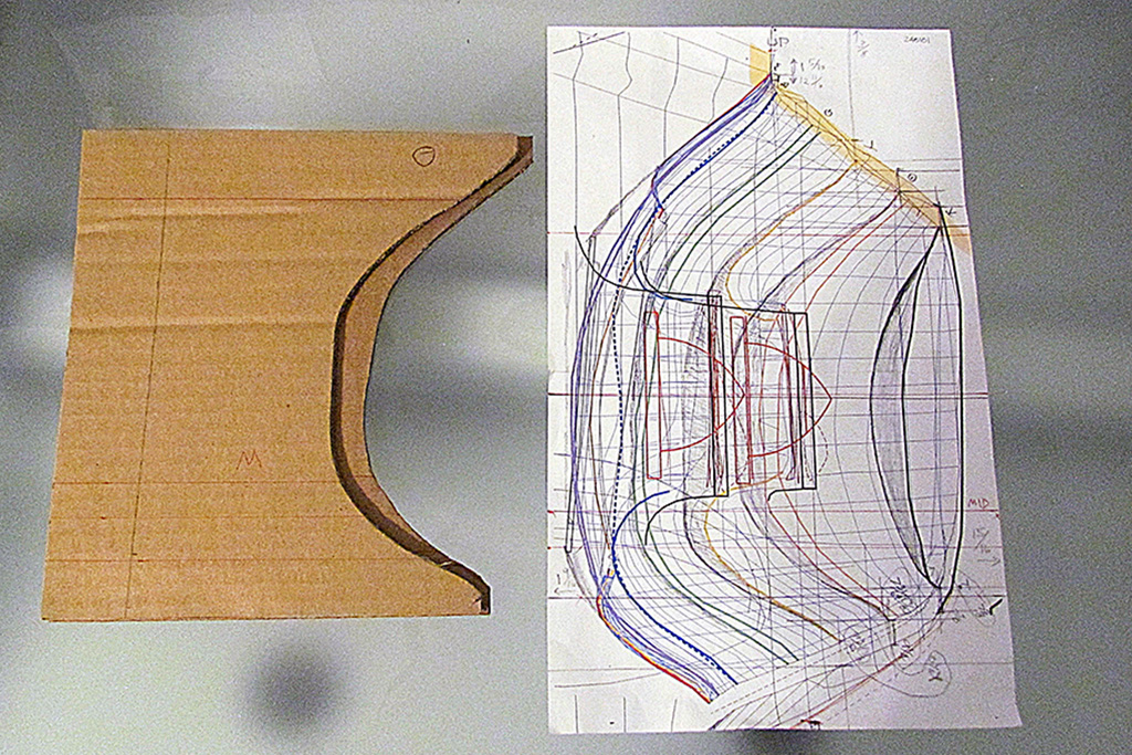
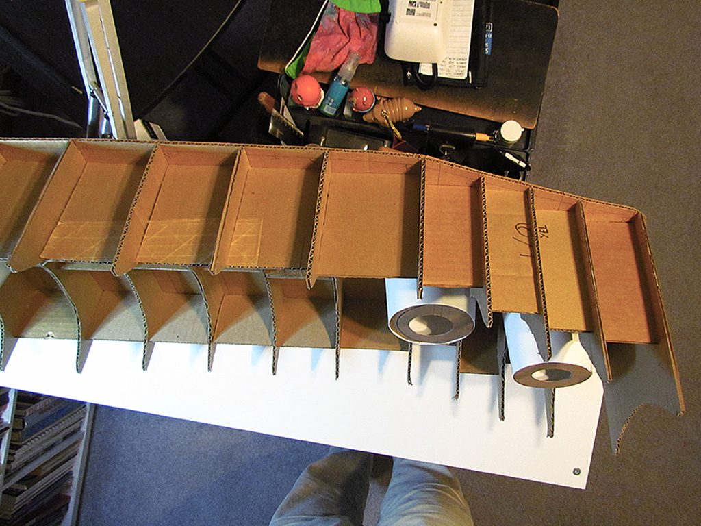
1st ROW - Male Contour Form
(L) Making the positive (male) contour form.
(R) The completed form.
2nd ROW - Female Contour Form
(L) Looking at the remaining contour halves, I realized I could (SHOULD) make a negative (female) form, which would be the actual surface!
(CL) Looking at how I made my drawings, I realized I needed to trim some more off of those on the canted-out wings. The idea is to build up the space between the contours with spray-on insulation foam and sand down to the forms to shape. The cardboard pieces show the difference. The drawing was my corrections.
(CR) Here is the form nearly all built up.
(R) And setting the final contours.
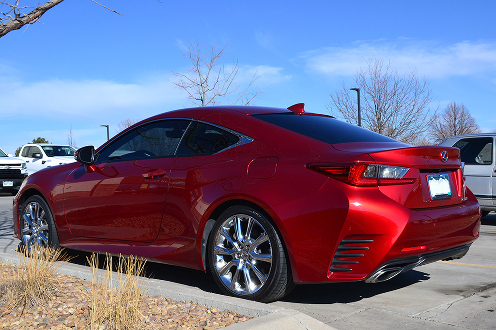
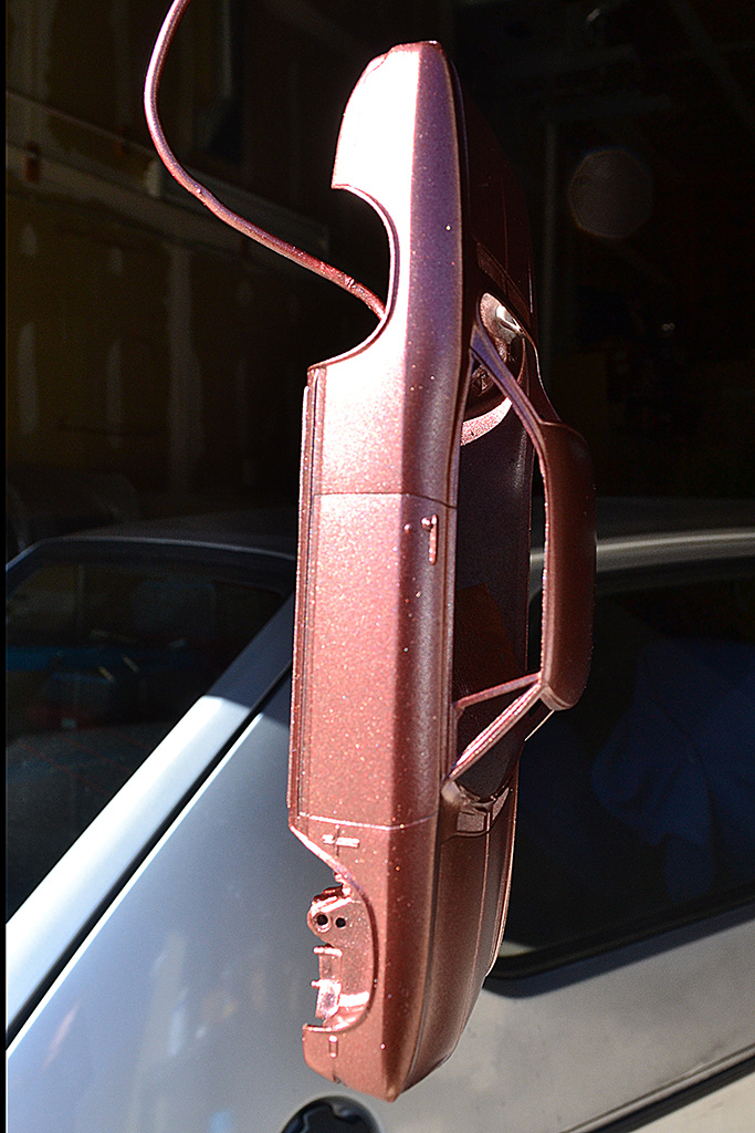
3rd ROW - The Closest Color???
(L) One of my designer friends recommended a color on the Lexus, 3T5 Infrared.
(CL) To my relief and delight, an SC 350 turned up at a local car parts store.
(CR) I would see it there from time to time and got to talk with its owner.
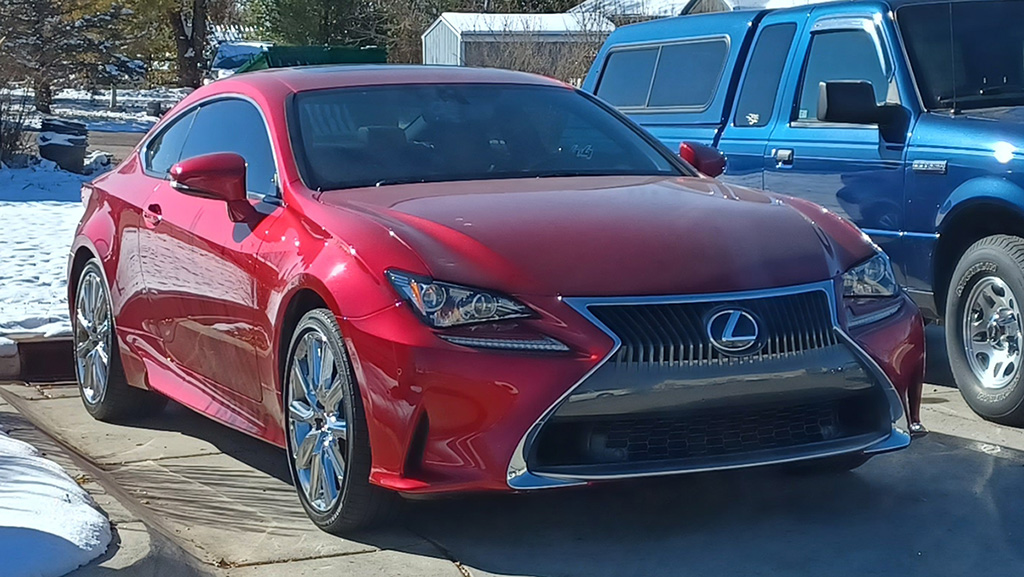
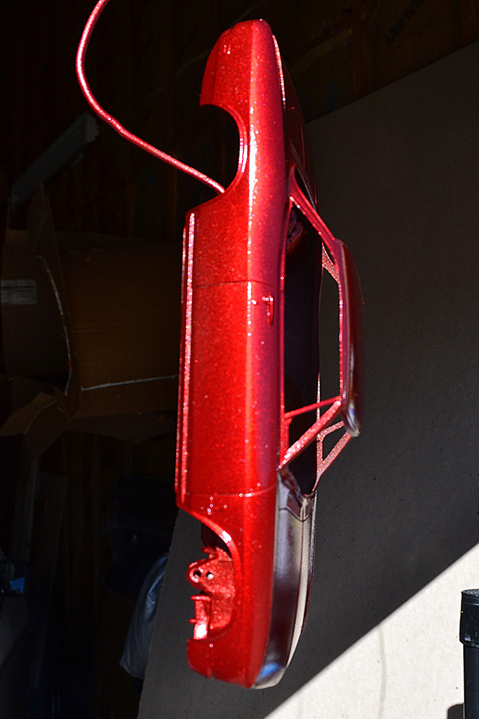
(R) This is what it looks like in the blue-sky sunlight.
4th ROW
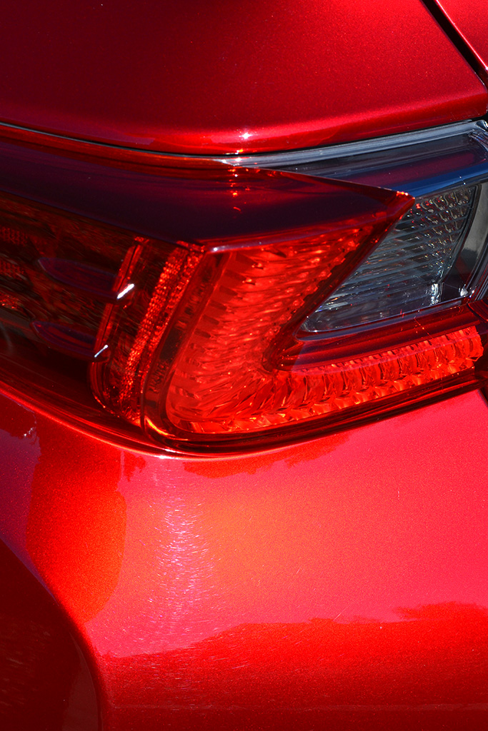
(L) And this is what is looked like in bright sunlight one morning.
R And this is what it looks like under an overcast sky. Note the differentshades between the fenders and the door.
5th ROW - Building the Taillight Cones
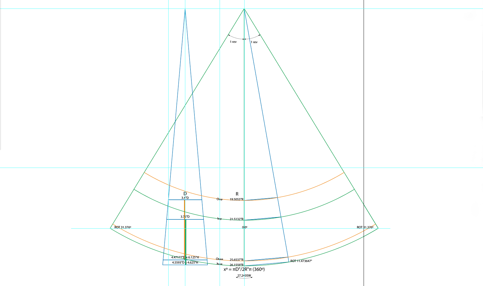
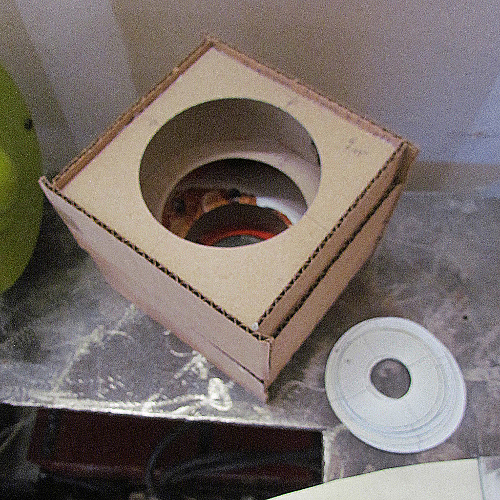
(L) I laid out my cone pattern using basic drafting techniques, and cut out circular bulkheads for the top, middle, and bottom of each cone.
(CL) The bulkheads have a hole in each so I can reach down thru it when glueing and foaming.
(CR) And then I cut out space to insert the cones into the contour form.
(R) Top view. After studying it, I was uncomfortable with their size and heights and positions. Time to go back to my drawings, before I go any further.
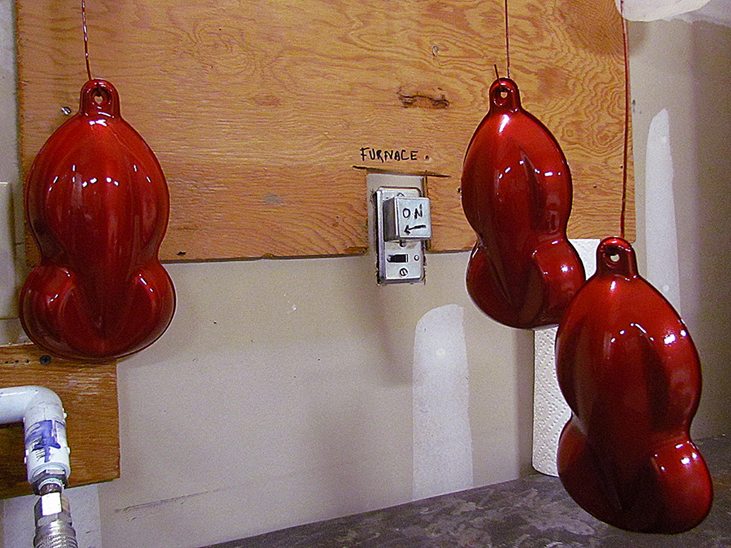
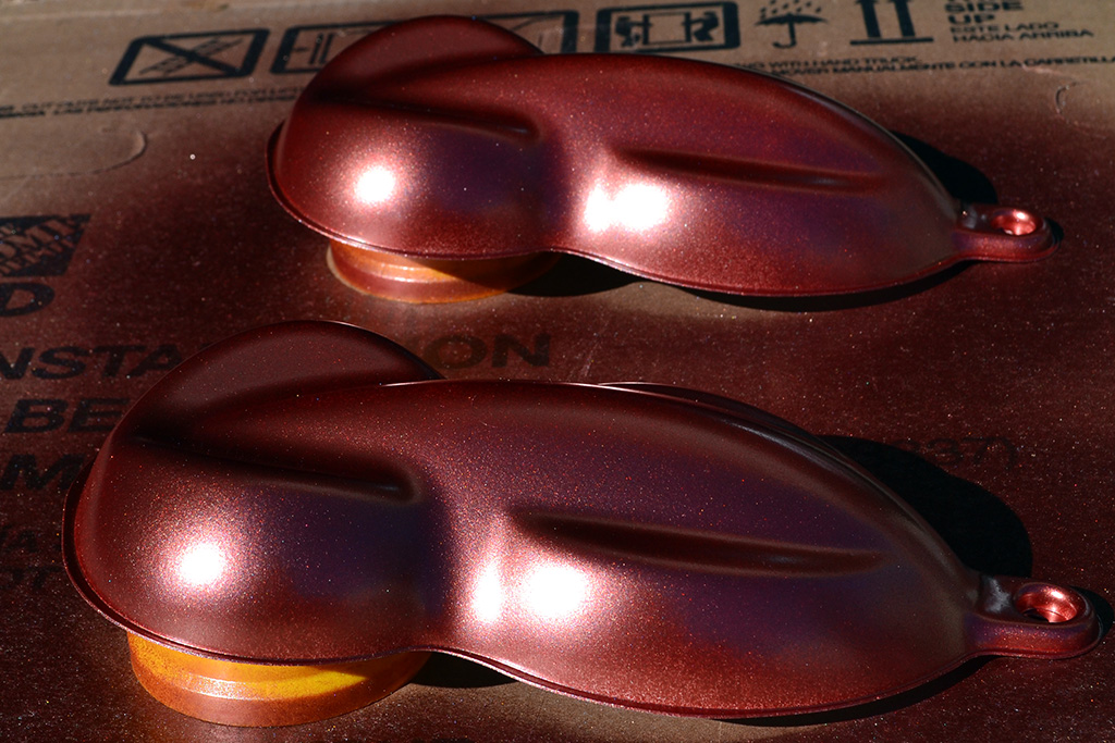
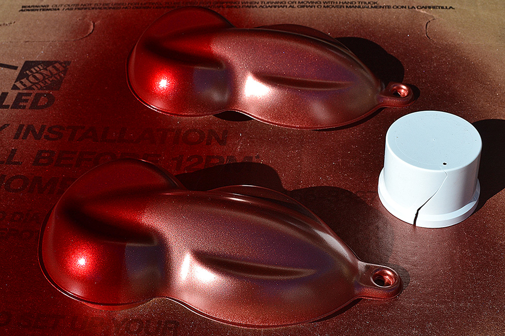
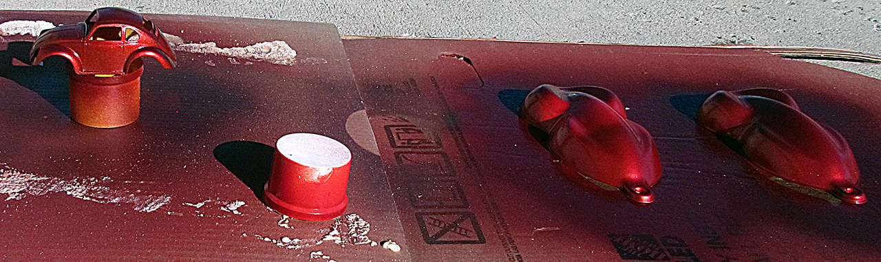
6th ROW - Test Paint Barcelona Red Micah
(L) The weather turned warm and I ordered what I had orignally been told was the Lexus color: 3R3 Barcelona Red Micah. Here are my speed forms under regular indoor lighting.
(CL) And here they are taken with a flash - a whiter light and with stronger highlights.
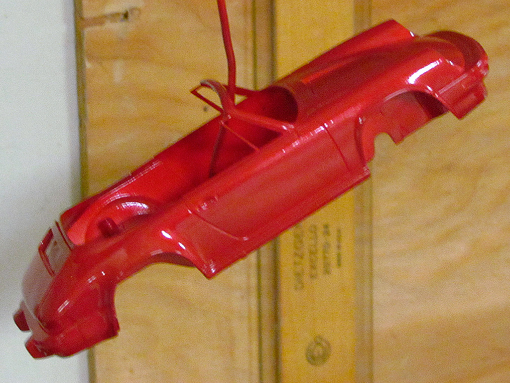
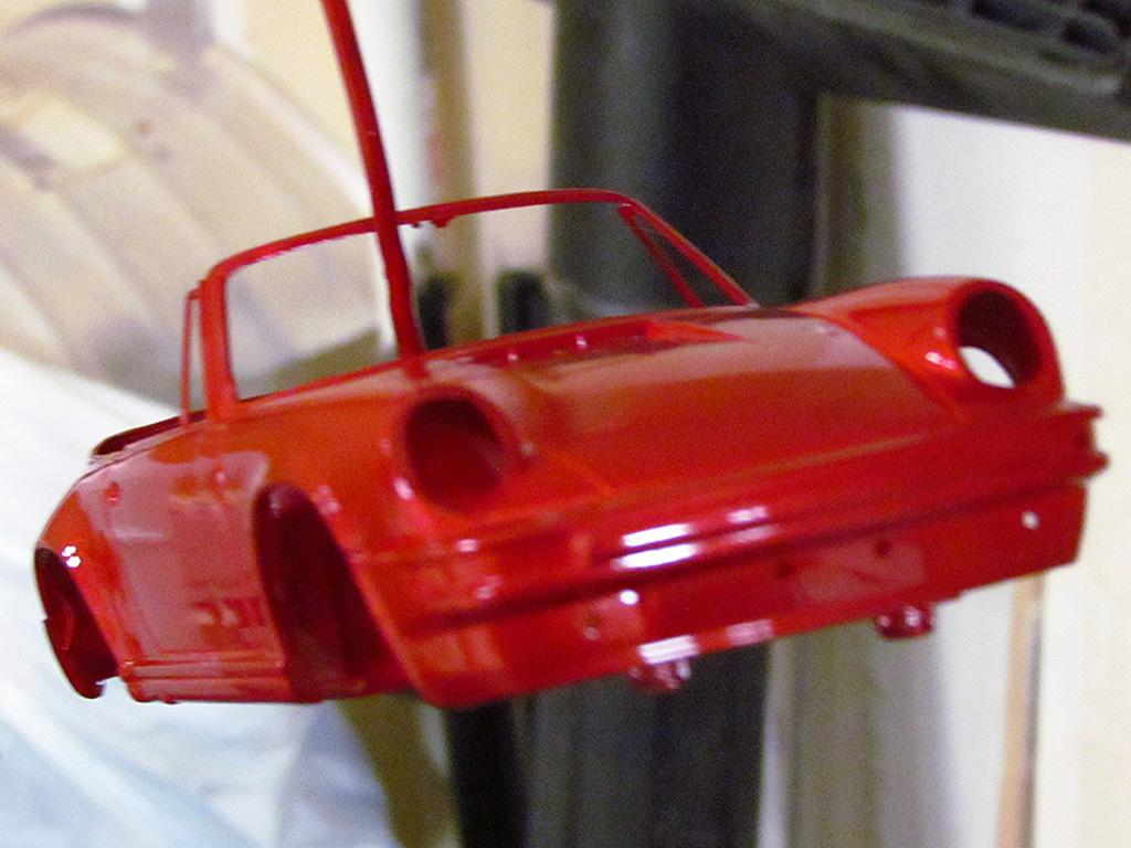
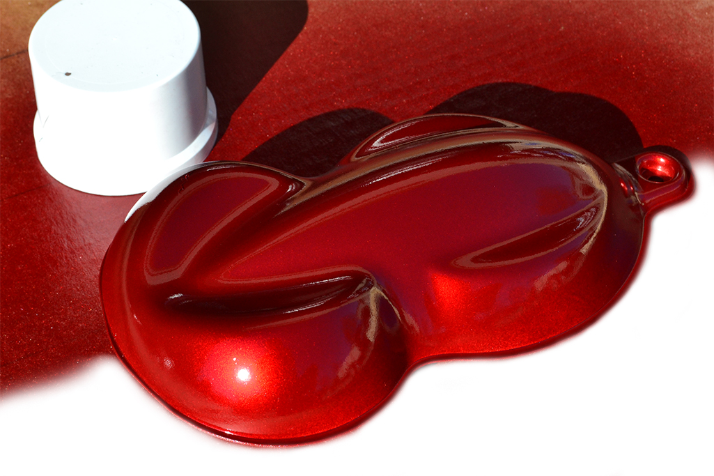
(CR) I tried it on a model Porsche kit as well.
(R) It looks as different in the photos as it does in real life. The speed shapes have three good coats of a single stage paint, while the model has only two. Both are on top of white plastic. And finally, there is a 2K clear topcoat for a shiny, smooth, hard gloss.
7th ROW - Visualizing Changes
(L) These first two photos are to visualize what the car would look like with a flush gas cap cover, instead of a flip-up LeMans cap. I have not been able to find one the right size, that I deduce to be about 3-1/2" diameter. I either find a 5" version or a 2-1/2" version, both of which look out of proportion.
(CL) I have made a circle, much like on the Aerovette, where the cas filler cover would be in place of the LeMans cap.
AND. . . I also deleted the fender mirrors and replaced the funky exhaust pipe with the straight pipe from the original release in April 1963.
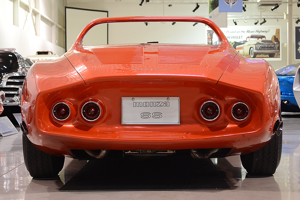
(CR) Here is a before and after version of the rear license. I have always been bothered by the rear plate mount. It is beautifully sculpted into the Kamm cove, but it looks too big - especially too tall.
(R) My thought is to make a bracket that grips the plate on the sides, with a built in light, and mount the bracket to the cove at a single mounting point. The plate would, in effect, float above the cove. This, and the use of the original headlight covers, would be the only departures from the reproduction.
8th ROW - Visualizing Kamm Cove
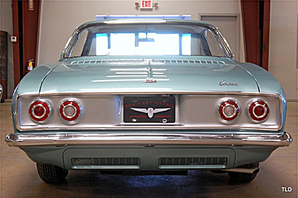
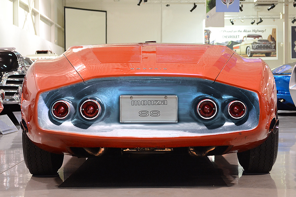
(L) As an inspiration, I took the brushed aluminum-looking tail panel on the 1965-69 Corvairs and tried that out on the deeply dished Monza SS cove - quite unlike the flat version on the Corvairs.
(C) I tried something not quite chrome, but more polished than brushed metal as was on the Corvairs.
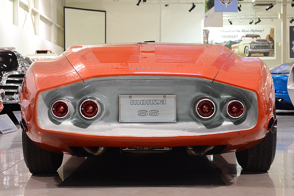
(R) The feedback I received about the near-chrome cove was that it was too showey. Argent paint was suggested instead. Here's how that might look.
February
1st ROW - Back to the Drawing Board
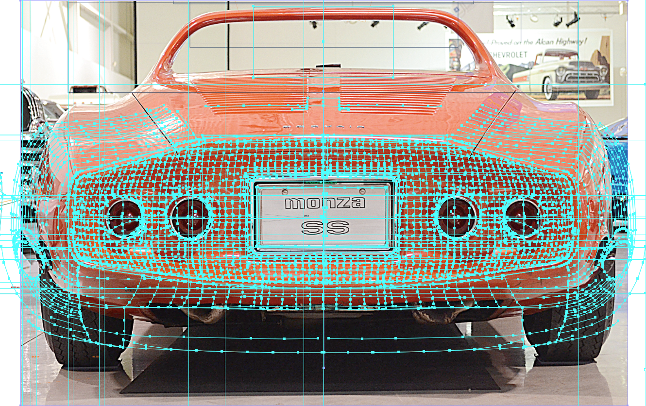
(L) I pulled up three good views, as close to orthographic as I could find. This top-down view should give me a good measure of the taillight widths and positions.
(CL) This near, side view gives me the best idea of the height, or projection, of the taillight from the cove.
(CR) This straight-on view will be matched to what I derived from Photomodeler. In the end, I gave greatest weight to the PHotomodeler drawings, and just made adjustments to sizes and positions.
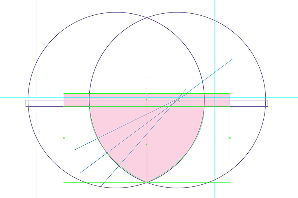
(R) And here is the layout for the inside (green arc) and outside (orange arc) taillights, based on a cone angle of 10 degrees (5 degrees from vertical each side as seen from a side view). Then a simple drafting layout solution is done. The circumference ("1 rev") is doubled to make a doubled wrap cone shape from the pattern, a 31 degree slice of the total cone circle.
2nd ROW - The Final Set???
(L) I even discovered my taillight lens drawing was incorrect. So I decided to also correct the bullet profile at the same time, making it a circular arc instead of hand-drawn. The pink area is the rescaled old lens drawing before correcting the curvature.
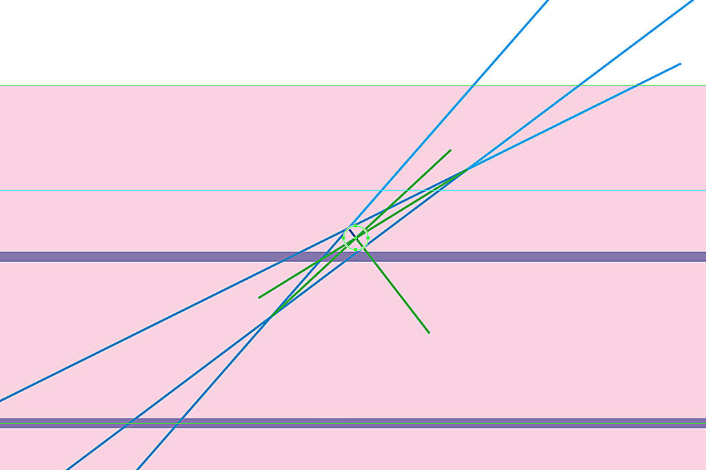
(CL) Using the handdrawn curve, I found the midpoint of the hypothetical curve radius. Actually, my three perpedicular radii did not go to the same intersection point, so I needed to do a contructed average. And that worked very well!
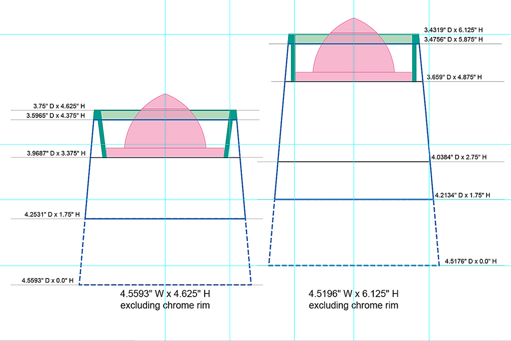
(CR) Only THEN . . . could I create my final drawing. I created these sections to also place the lenses, the chrome trim rings on the end, and the placement and diameters of reinforcement bulkheads (bold black lines.)
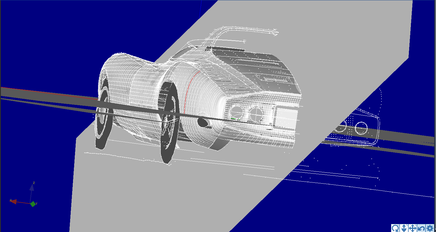
(R) After all the work last summer surfacing the 3D model, I established some XYZ planes and oriented it to the model. Wow! it looks good from this angle!
March
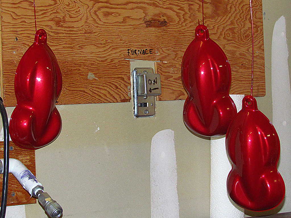
1st ROW - 3T5 Paint Test
(L) Speed shapes with base color.
(CL) The same with a single coat of midcoat on one-third of the shapes.
(CR) Speed shape completely covered with one coat.
(R) Base coat on a 1/25 Corvair model. This gives a better idea of the metallic color and reflectance.
2nd ROW
(L) Corvair body with one coat of midcoat color. The clearcoat did not change it any.
(CL) Second test of 3T5 to see if I could lay down a lighter midcoat. The cap shows the midcoat color on a white ground color. The Beetle on the left was my best attempt at a light coat. It looked dull until I applied the clearcoat.
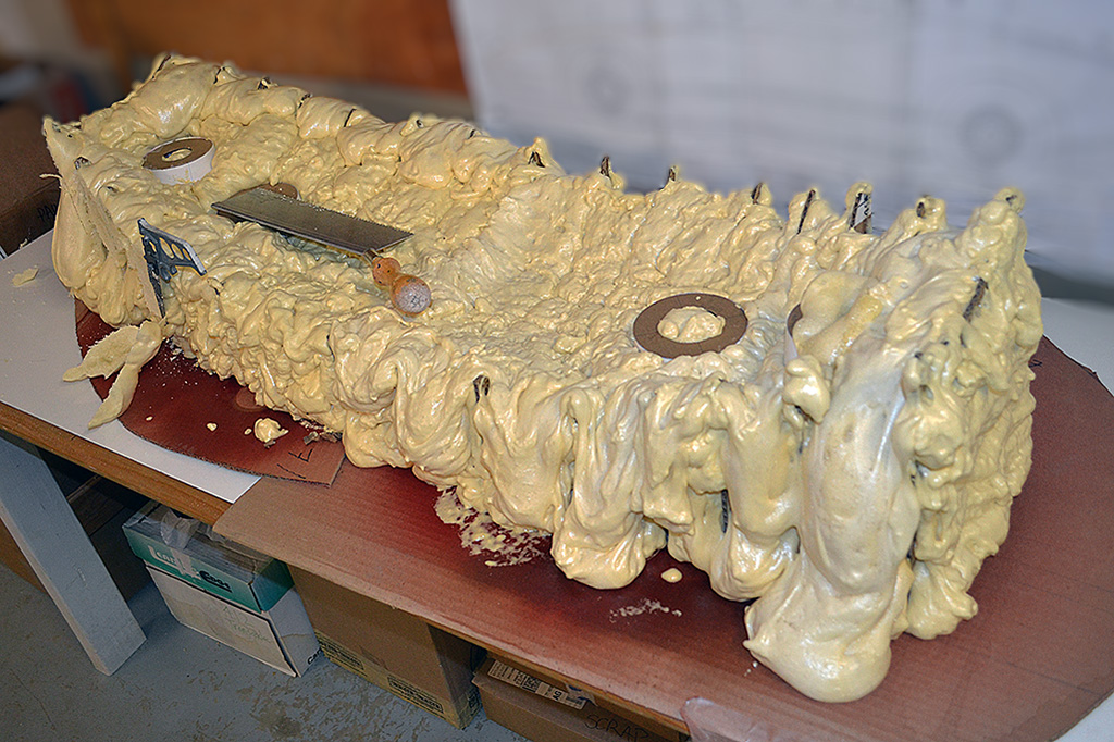
(CR) Meanwhile I fabbed a gouging blade for the handdrill to cut hood vents. It was too course and uneven when cutting thru foam.
(R) Paint and drill bit happened while the spray insulation foam was setting in the Kamm cove form. It was hard to build it up on the rim. It looks pretty ugly at this point!
3rd ROW - Carving the Cove
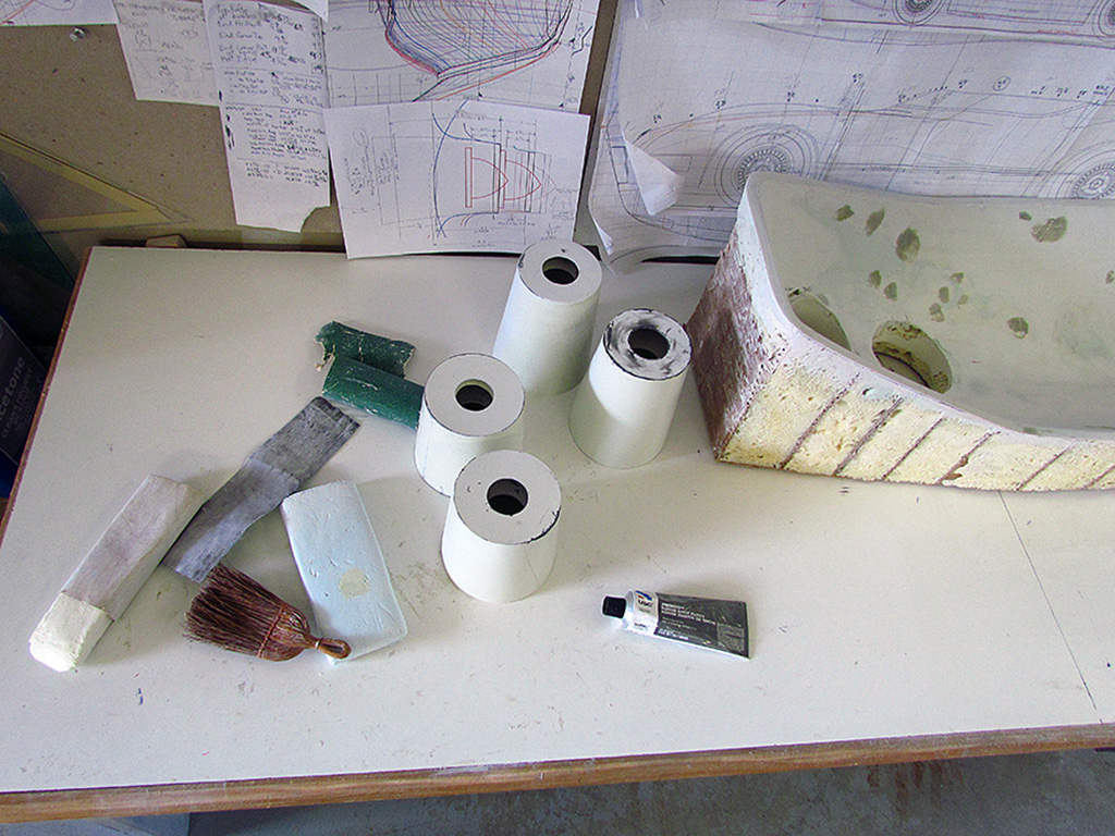
(L) After trimming with a blade the excess on the outside, came the samding with a 40grit disc on the handdrill and using my small handrasps to carve out the cove.
(CL) There were lots of cavities where the foam did not expand into. I applied a 2nd layer too quickly so that the 1st layer was not exposed to air and could not cure well. This compares the first trial cove above with the second trial cove. The sheet foam is nicer to work with than the sprayfoam, but the contours make it more accurate to carve.
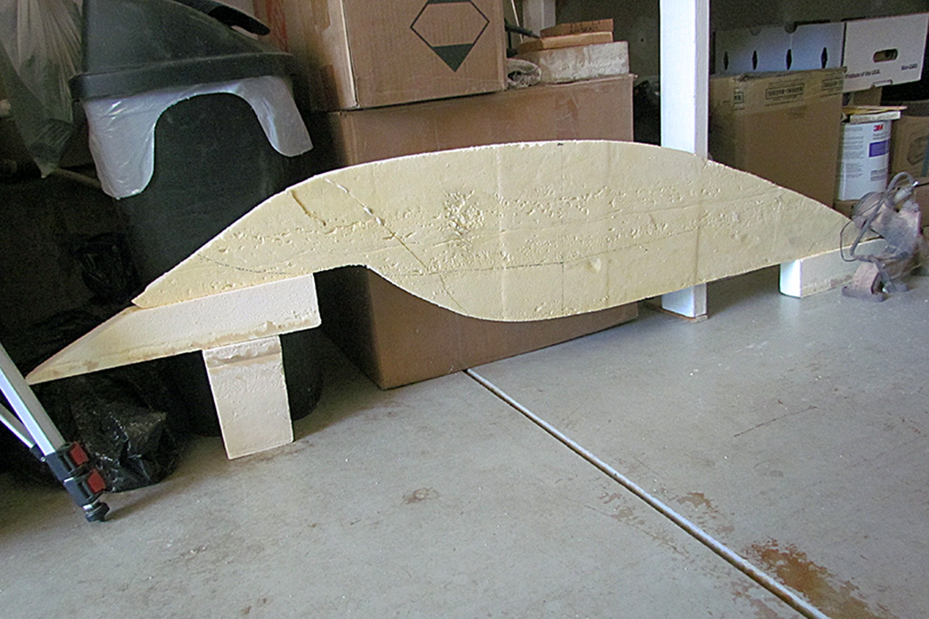
(CR) The final step in carving was shaping the ends. I glued a block on each end, traced my outline from the end view, then the side view, and sanded to shape.
(R) The side view and my tracing pattern.
4th ROW - 1st Bondo
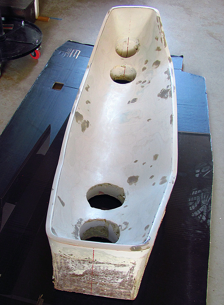
(L) The ends, trimmed to shape.
(CL) A view looking into the cove from behind.
(CR) The first coat of Bondo.
(R) Hand sanding would take hours. I used a coarse disc meant for metal and got most of it sanded down.
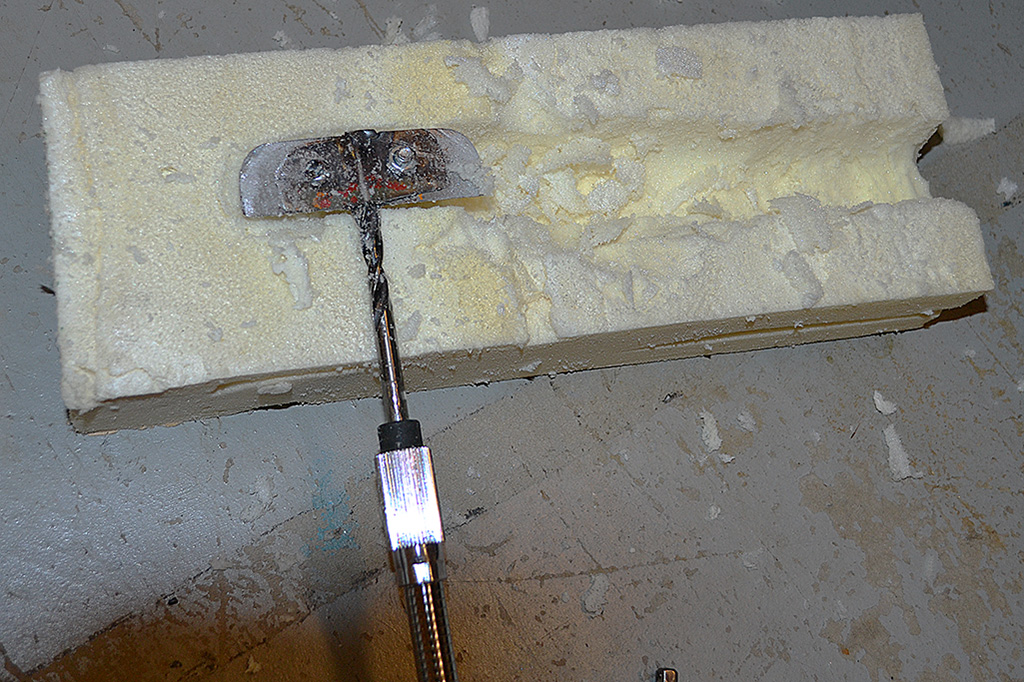
5th ROW - Rear Deck Hood Vents
(L) My 2nd attempt to carve the rear-deck hood vents. I shaped a scuffing disc to the vent contour, made a sliding holder for the drill, and slowly, carefully ran it along lines drawn on the foam. Note the protruding pieces in the vents to reinforce the material inbetween the vents holes.
(CL) The final result.
(CR) The first three or four vents will need some fixing, and on a place or two the disc grabbed and went past the ending lines. All will be corrected at surface-hardening.
(R) The blue joints had to be cut with a matte knife and the blue glue dug out, or else it would have destroyed the shape of the disc.
April
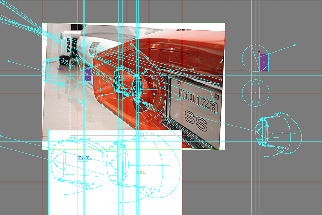
1st ROW - Getting Ready for Glass and Top
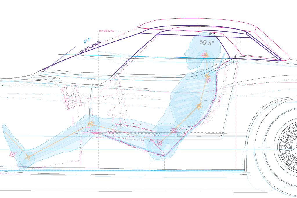
(L) How small can I make a removeable top? Somewhere between the purple and the magenta versions. The figure represents my expected seated position.
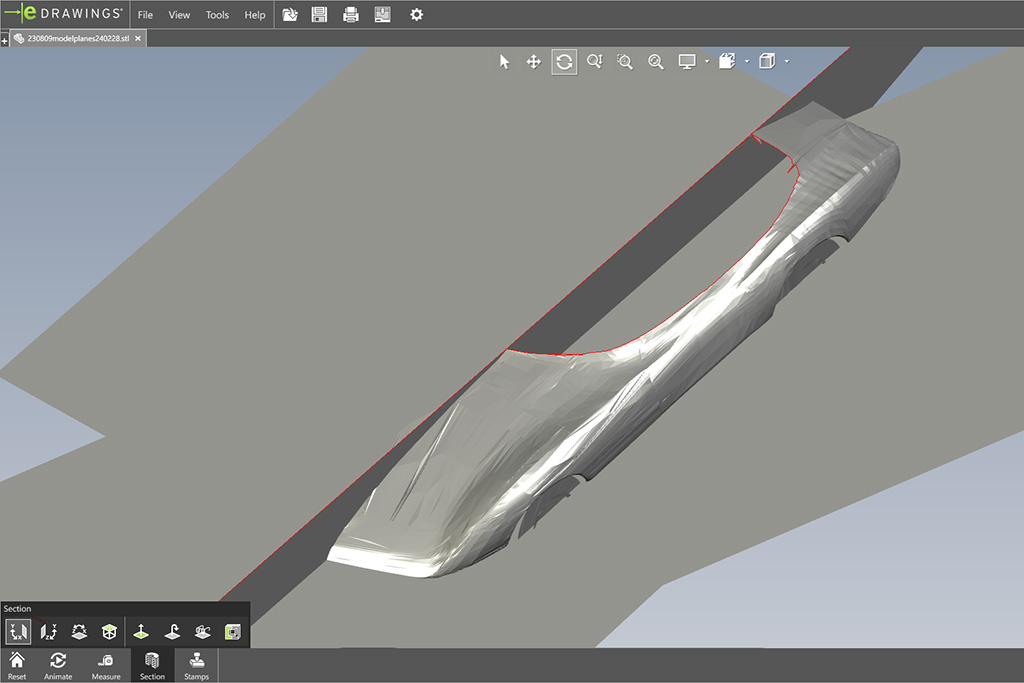
(CL) The 3D surface model in eDrawing showing a cut in red thru the windscreen passing thru the front base.
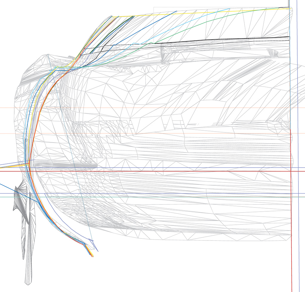
(CR) Front view of combined cuts showing how side window curvature changes from front to back.
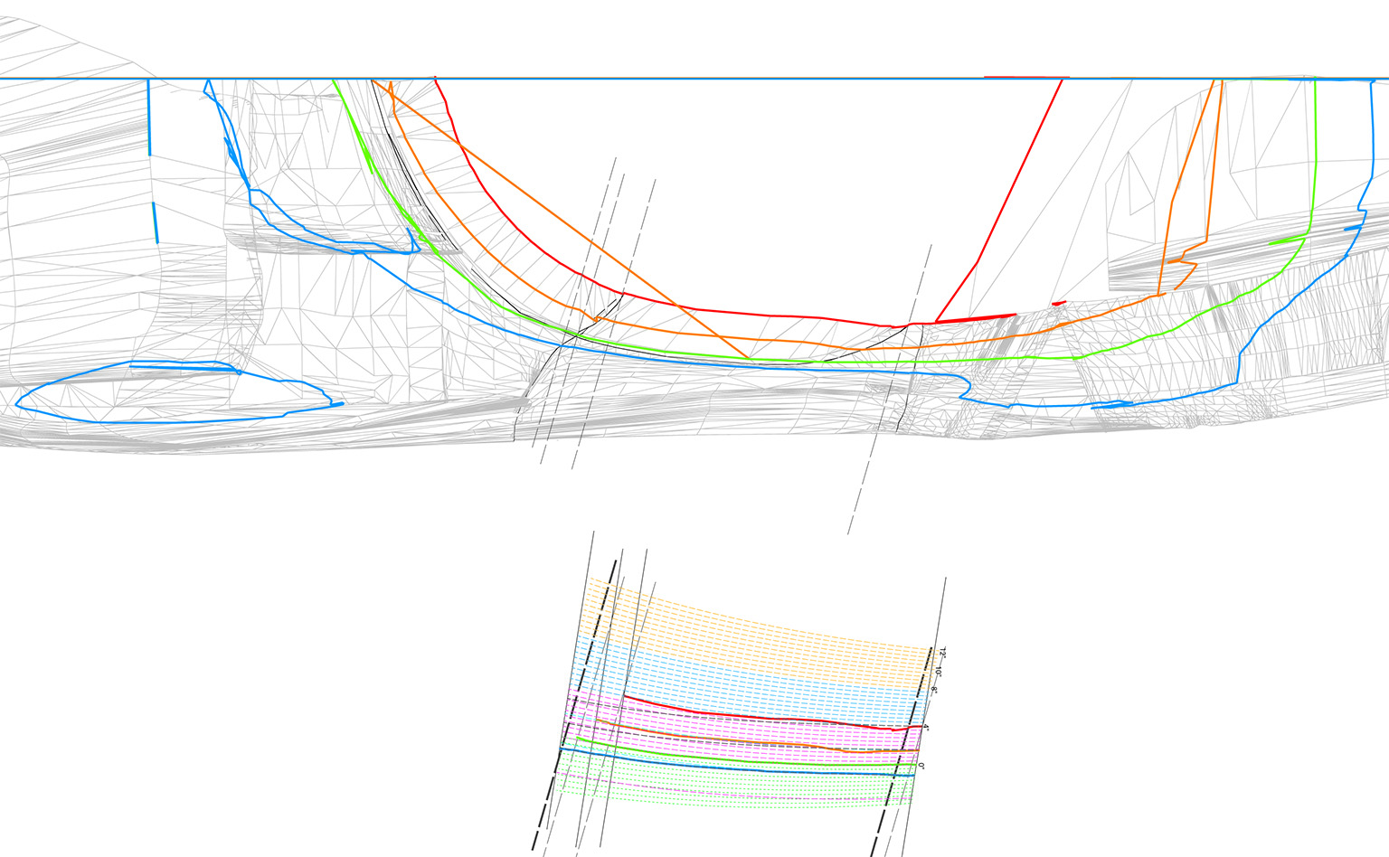
(R) Top view showing cuts thru windscreen and side glass. The bottom drawing shows how the curvature changes from bottom to top. The green line represents the orthgraphic top view shape of the glass curvature at the level of the door window slit.
2nd ROW - Cutting off the 1st Taillight Cones
(L) Cabin outline in place on the chassis.
(CL) The 1st taillight cones.
(CR) Another view. The coated surface was just going to be too much work to smooth, they are too delicate, and too unlikely to be nicely rounded when done. They hafta go!
(R) The first taillight cones freshly cut off.
3rd ROW - 2nd Taillight Cones
(L) The box to form and hold in place the new sheet styrene taillight cone patterns while drying.
(CL) A pattern in place. Some styrene cross-sections above and a test paper cone standing beside the box.
(CR) A cardboard spacer to help hold the pattern in shape while drying.
(R) Adding shapes as needed.
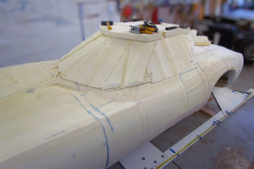
4th ROW - Top Profile Piece on Foam Body
(L) 3/4 front view of the profile foam piece in place on cabin portion of foam body.
(CL) Side view
(CR) 3/4 rear view of the profile piece in place. It does give some idea of the final appearance. . . and it looks much too short ans too small for head room.
(R) Trying out the profile piece next on the chassis.
5th ROW - Top Profile Piece on Chassis
(L) From the passenger side. I am sitting in the driver seat. One cannot see my head yet behind the profile piece.
(C) But from the driver side, it sure looks like my head IS above the profile piece!
(R) The level says it is J-U-S-T under the profile outline, which means I must tilt my head down to fit under it. I decide I will need to raise the roof (so to speak) at least 2 inches and hopefully no more than 3 inches.
May
1st ROW - Confronting Reality
(L) Comparing and evaluating what I made with the near-ortho top view photo.
(R) Contemplating the consequences of cutting what I have made in half against the possible negative outcomes. . . and cringing.
2nd ROW - Doing the Deed
(L) The two halves of the Kamm freshly cut with a hacksaw blade.
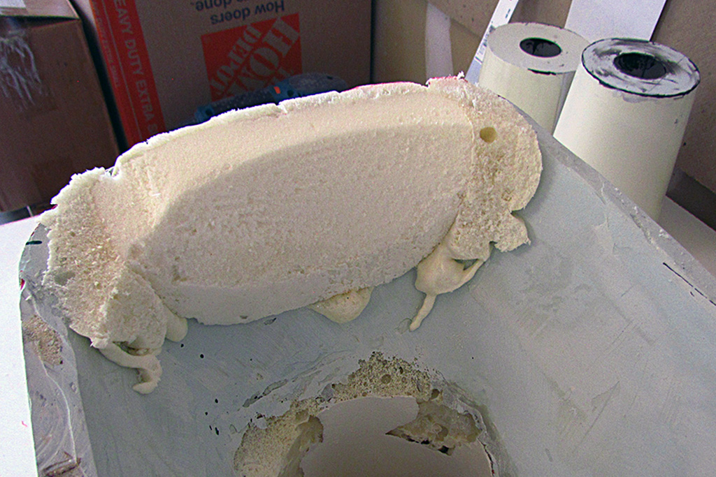
(C) The new spacer being glued on with my new foam technique.
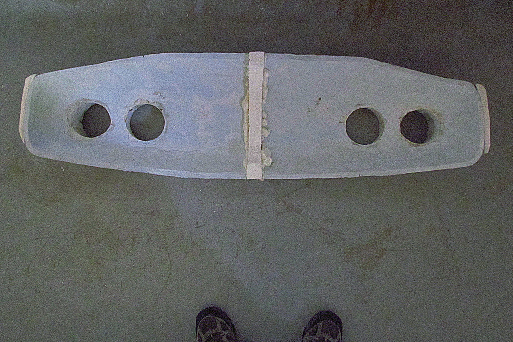
(R) The complete Kamm glued back together. It is surprisingly sturdy to pick up and handle!
3rd ROW - While On Vacation
(L) Mt. Hood
(CL) Multnomah Falls
(CR) Ezra Meeker House
(R) Museum of Glass (MOG) Hot Shop
4th ROW - Back at It
(L) Testing how to shape the expanding insulation spray foam. A weight over a wax paper sheet. The sheet had to be removed for the foam to cure in the center area.
(R) The spacer is sanded down and the Kamm is leveled.
5th ROW - Adding to the Ends
(L) Foam-gluing more foam to the outside edges.
(CL) Rough shaping.
(CR) Shaped to match the outer edge contour.
(R) Closeup of an outside edge.
6th ROW - Beginning the Top
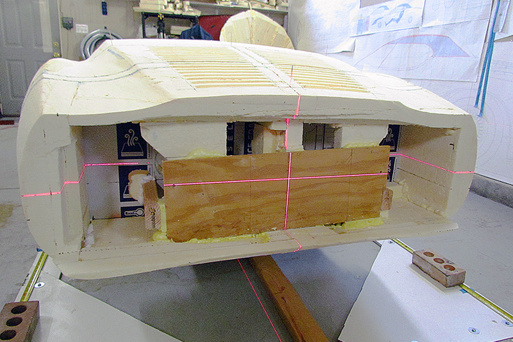
(L) A center contour backbone to get started and to hang panels onto.
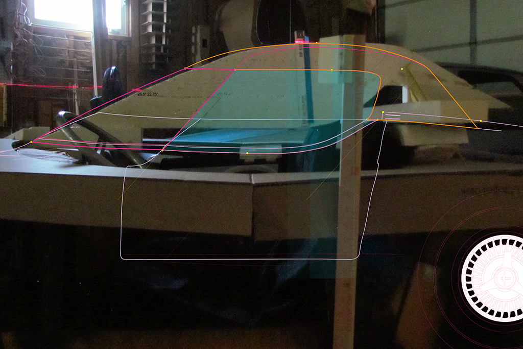
(CL) An approximate idea how it dimensionally fits, with the car side view line drawing superimposed. Remember - the drawing is accurate in this photo to the centerline of the car, as represented by the foam contour.
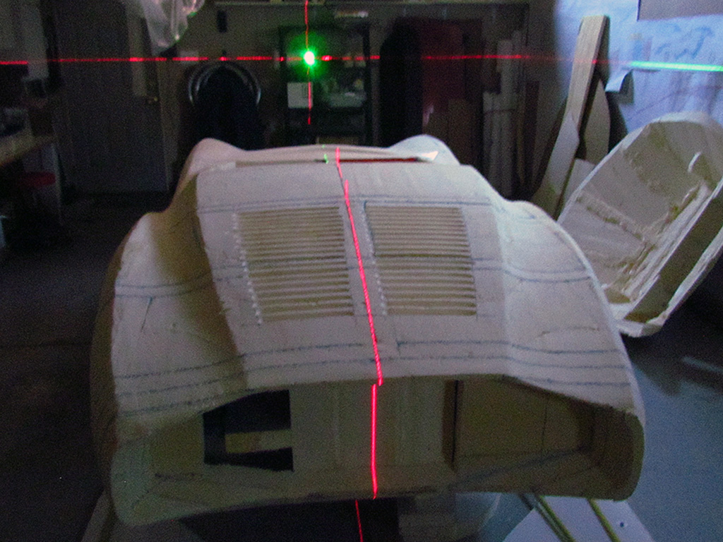
(CR) Sort of a top, look-down view of the centerline as cast by the laser.
(R) And as seen from the side with the image centered on the point where the hood line meets the windshield.
7th ROW
(L) Front view of centerline laser.
(CL) Adding another panel to the front and a side window panel.
(CR) The same seen of the driver's side. It really does not look like the front glass and the side glass can meet given their angles of inclination.
(R) Stereograph (parallel viewing)of the rough shapes.
June


1st ROW - The New Kamm Pattern
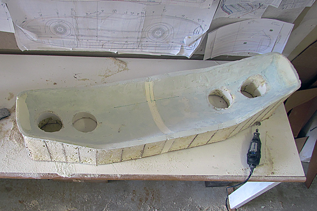
(L) Here are the different attempts I have done this last year to create the Kamm cove: 4 chunks of foam and 2 patterns. . . so far.
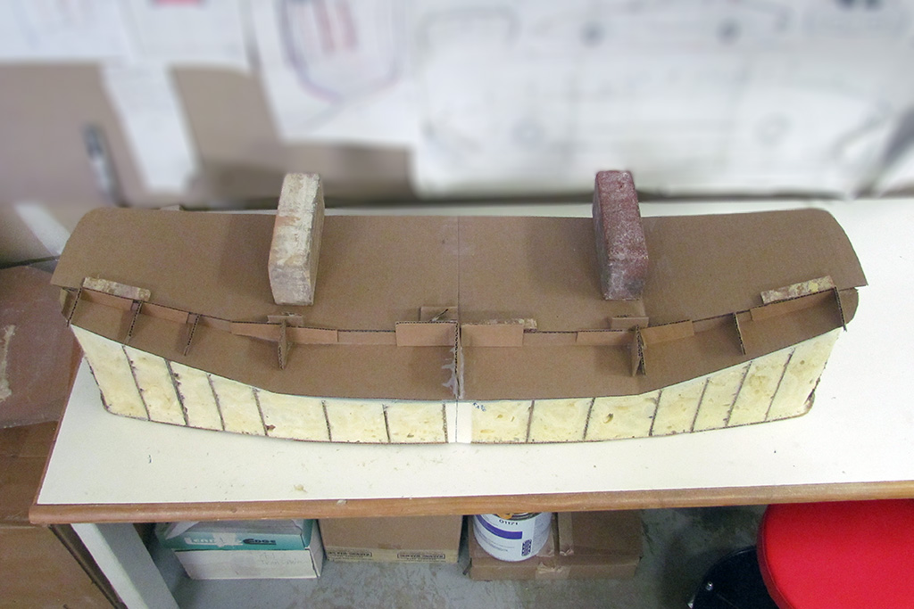
(CL) Here is the 3rd pattern in place. The bricks hold it down where the wings bend out.
(CR) Looking along the lower edge line.
(R) Looking along the upper edge line.
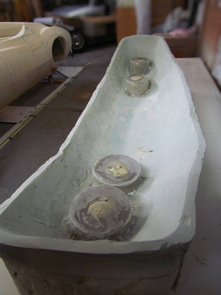
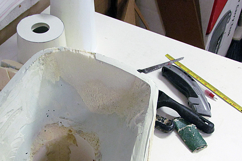
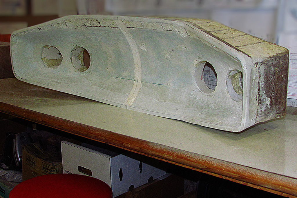
2nd ROW - Edge Rim Defined and Cove Roughed Out
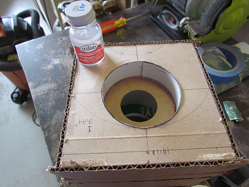
(L) Here's the Kamm cove after defining the outer rim to a width of 7/16th inch. This shows the cove seen mostly straight on after rough contouring it back down.
(C) The same seen from the passenger side.
(R) And the same seen from the driver side.
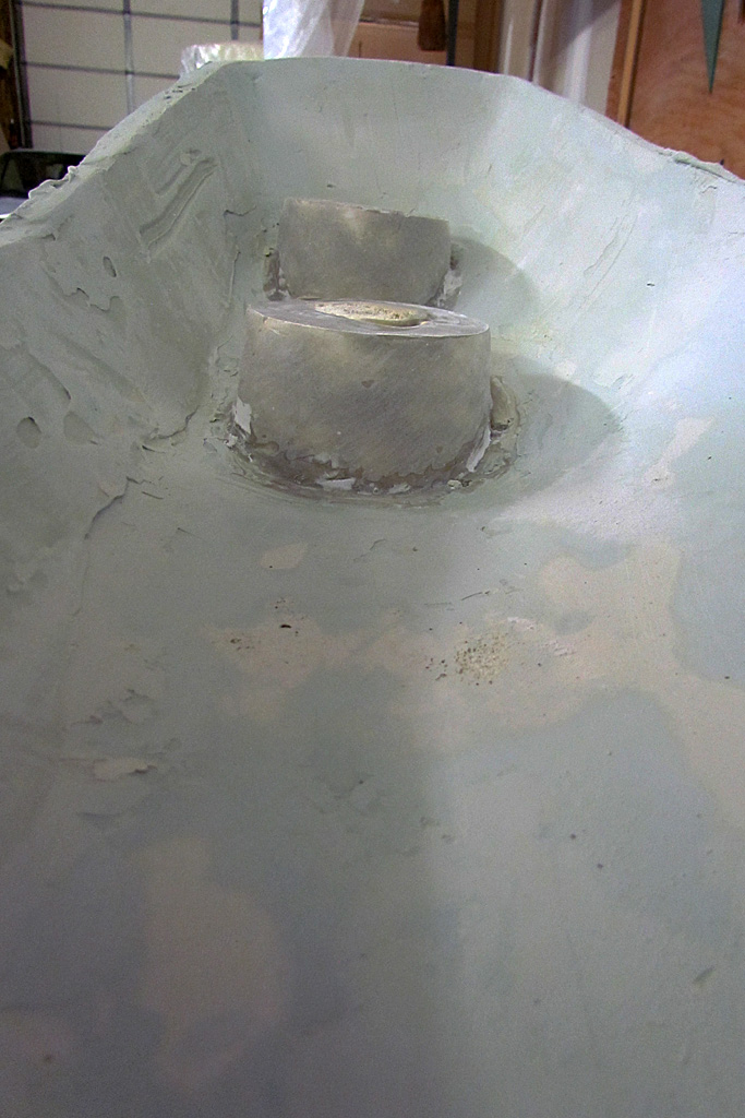
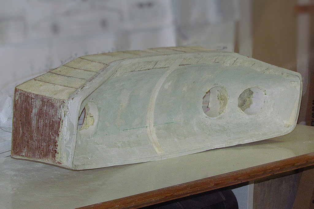
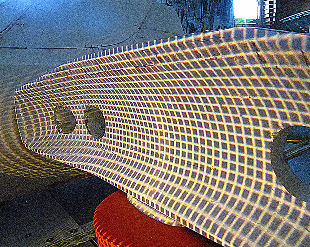
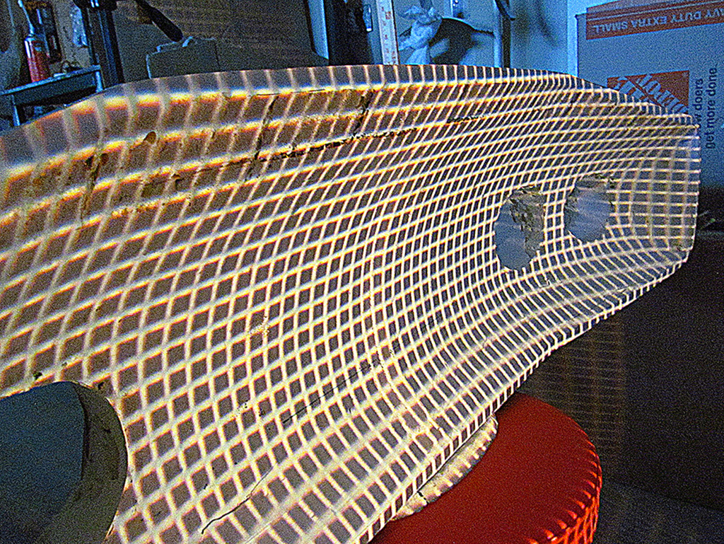
3rd ROW - A Check on the Contouringt
(L) This is a contour line check of the cove. I projected a grid pattern onto the cove.
(C) Looking across it from the right side.
(R) Looking across it from the left side.
July


1st ROW - The Pop-Top Side Windows and Top
(L) The laser line shows the height of the windscreen on the original 1963 car.
(CL) The line is a continuation of the line extending from the rear deck. This is as far down as I want the side windows to roll.
(CR) The top added seen from the front...
(R) ... and seen from behind.
2nd ROW - The Pop-Top Rear Window
(L) Added the fill-in pieced for the B-pillar. The laser is an angle check.
(CL) The rear window panel in place.
(CR) A 3/4 rear view.
(R) And it all in place with the driver side well roughed-out. Note the whitish center line on the windshield.
3rd ROW - The Pop-Top: An Alternate Possibility
(L) Seeing the reverse-angle cut of the B-pillar, I thought of placing the remainder foam piece from the top panel cutout on the roof.
(R It looked very 1950s, rocket-to-the-future modern. And it might be even useful if I placed lights in the wing-like side extensions. But better judgment prevailed. . . but for a few minutes, I was seriously excited by the possibility!
4th ROW - The Chassis Test
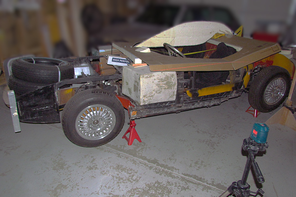
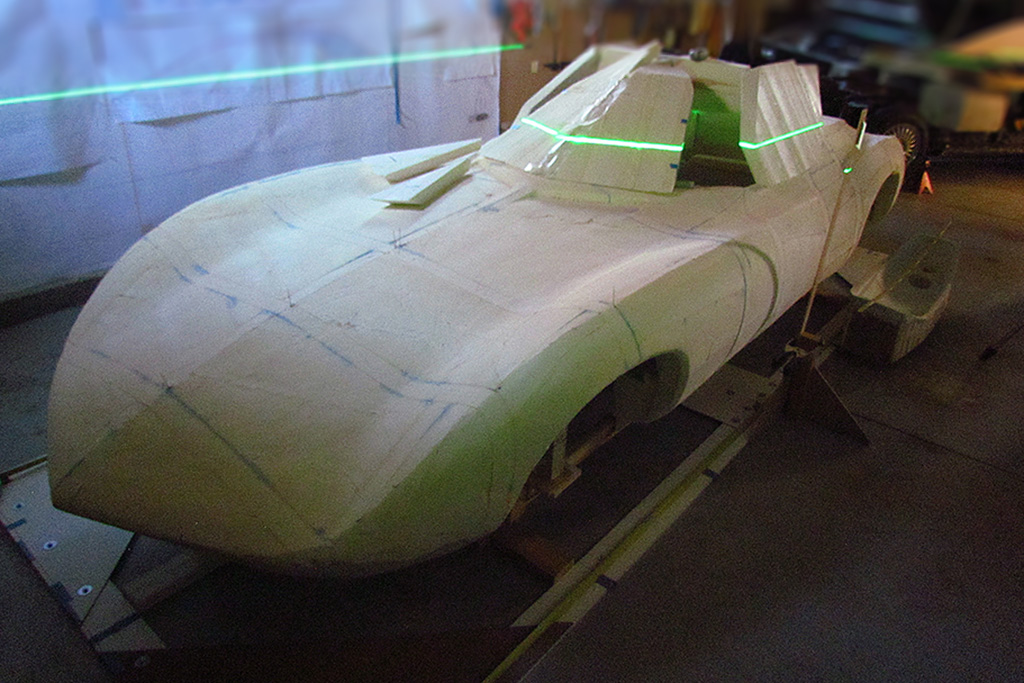
(L) Here is the completed pop-top in position on the chassis.
(CL) Here is a stereopticon view (parallel viewing).
(RL) And finally, after ten years, I could tell what it would be like to have a top over my head. There is only an inch or so to spare between the head and the roof, but it works. But I think the steering wheel will have to move closer to me by a couple inches, and maybe even have to be removeable.
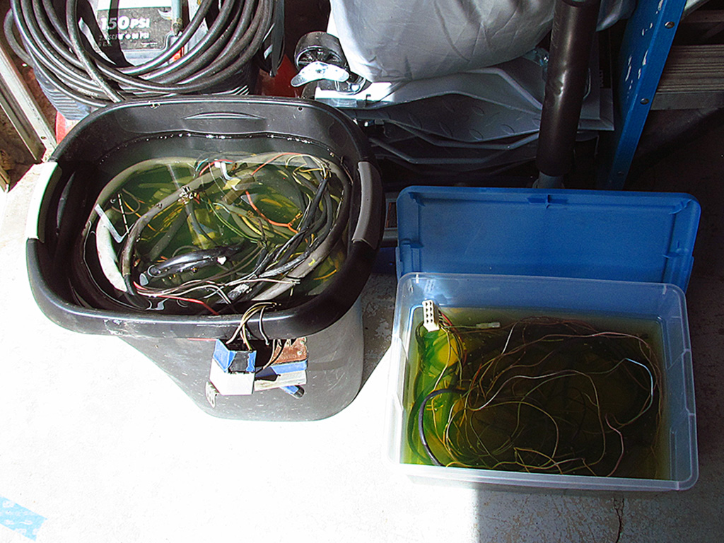
(R) What else could I do during summer weather? Well, I could finally unravel and soak my VW412 wiring harness in degreaser and clean that up.
August-October


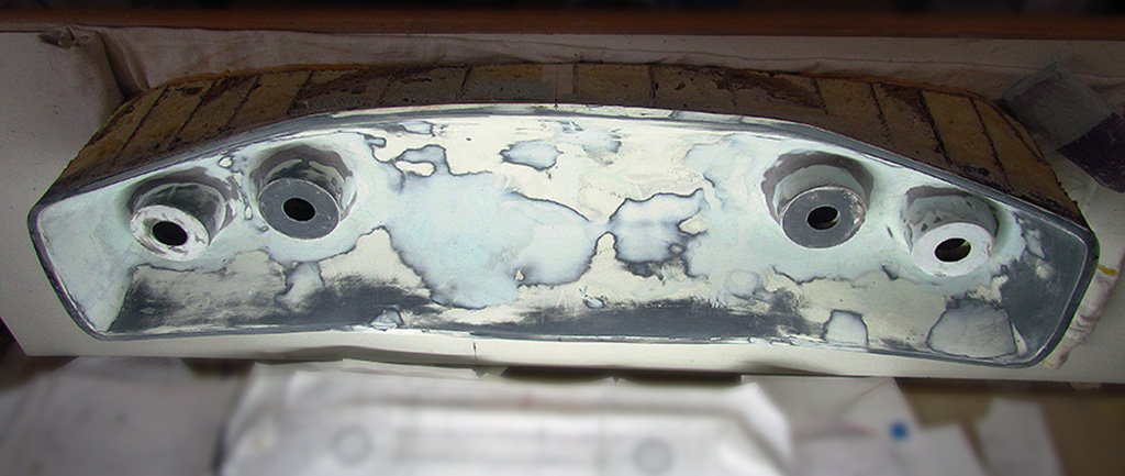
1st ROW - Kamm Cove Finishing
(L) Back to the taillights. While finishing the surfaces on them, I also was trying out putty on the blemishes on the cove surface. I do not find glazing putty as easy to sand down as Bondo. I am not sure when it's best to use it yet.
(CL) The cove with glazing putty.
(CR) A BIG MISTAKE! After sanding the glazing putty, I primed the cove and set it out in the sun to dry. BUT... it heated the foam, which expanded in the heat and cracked in various places!!!
(R) Lots of blemishes to gouge out and refill with Bondo.
2nd ROW - Refine PopTop, Engine Leak
(L) While the Bondo sets, I continue shaping the poptop. Here I am establishing the centerline - a useful datum if (when) I remove the top.
(C) A side view showing how I am working out the location and the slant of the side windows. Note that the angle at the front and back of the side window must be the same to be able to roll it up and down.
(R) And inbetween the cove and the poptop tasks, I work to get the engine to start again. I succeed, but quickly develop an oil leak. It's evident it is dripping from the pushrod tube on the #3 cylinder- a common culprit. Here I have removed the rocker arm for the #3 cylinder and removed the push rod prior to removing the tube and replacing the O-ring seals. After replacing the seals three times, the leak is greatly reduced. Maybe it will go away when I change out the break-in oil with standard 30-weight?
3rd ROW - Releveling Lasers
(L) On a whim, I decide to get my centerline in agreement 'fer shure' from both the front and back. Note how the red laser lines center on the green laser aperature.
(C) So I align the front and back lasers to overlay each other, even matching the horizontal lines on the wall. Note how the green laser lines center on the red laser aperature.
(R) Each vertical laser line falls on the aperture of the other. Notice how the toothpick blocks the laser lines from each, allowing one side to be red and the other be green.
4th ROW - Cove Placement, Adding Internal Frame
(L) While still working on cove blemishes, I test-fit the cove to the rear of the body, just to see how it looks.
(CL) It cannot fit totally inside the body cutout, but does give a good idea of appearance. I decide I will need to cut off the tail outline around the cove and rebuild it in foam after the cove is attached to the body.
(CR) The time has come to retrofit a frame inside the body to give it strength to prevent it breaking in half again. The cove will add weight and make the foam structure very fragile when handled. Especially when transported to the fiberglasser. Here the first rail has been placed inside the body. I will also add feet at each end to fit at each end of the base. I also fill gaps and seams with gap foam to make the panels more rigid.
(R) I also make repairs to the base and recenter it all, and clean up all the old markings. If all goes well, the body will fit right onto the base and the feet will fit up against the base, so it all holds into place.
5th ROW - Adding Taillight Cones
(L) At last, the taillight cones are glued into place - but not without a near disaster. The Gorilla glue I applied to the backside dripped all the way down the sides of the cones. Before it set, I scraped it off. Once dried, I had to sand them down.
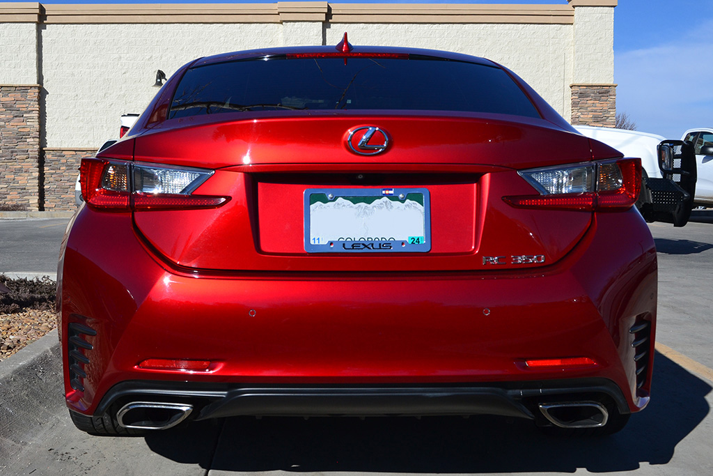
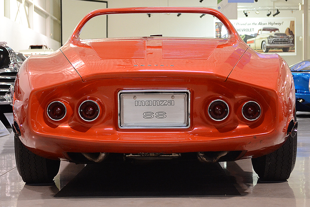
(CL) Here is a comparison view of the real car, with the license surround having been removed.
(CR) The last step is to add the fillet around the cones. I use the Aves modeling compound to do the job.
(R) While it dries, I foam (I glued it in with gap foam) the backplate in place to which I will attach the Kamm cove. It slipped some out of position as it set, so I had to extend the bolt holes to their correct positions.
November - Attaching the Kamm Cove
1st ROW - Attaching the Cove
(L) The cove after the last sanding
(CL) Test-placing the cove in correct position
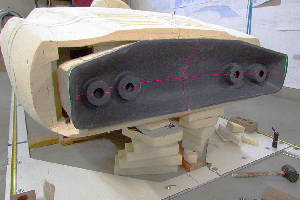
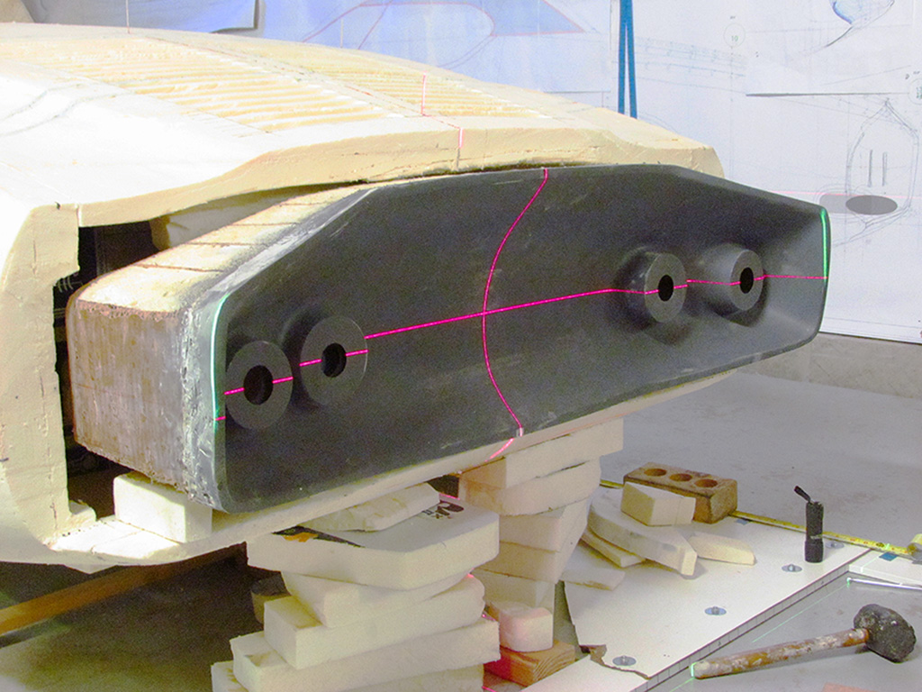
(CR) Laser alignment check. Note the vertical red line. The horizontal red line matches the body horizontal midline I have been using. Note also the vertical green line on the ends of the cove indicating those ends are the same lenght position from the nose.
(R) The side view showing especially the vertical green line. The green line on the floor is the actual measureable tailend length.
2nd ROW - Check Cove Alignment
(L) After all the months of effort and remeasuring, it all pays off. The horizontal line runs to the same height postion on each taillight cone, except the inner driver's cone, which looks to be about 3/16" high. Good enough for me at this point.
(R) Another view to better show the cove's concave curvature
(R) The
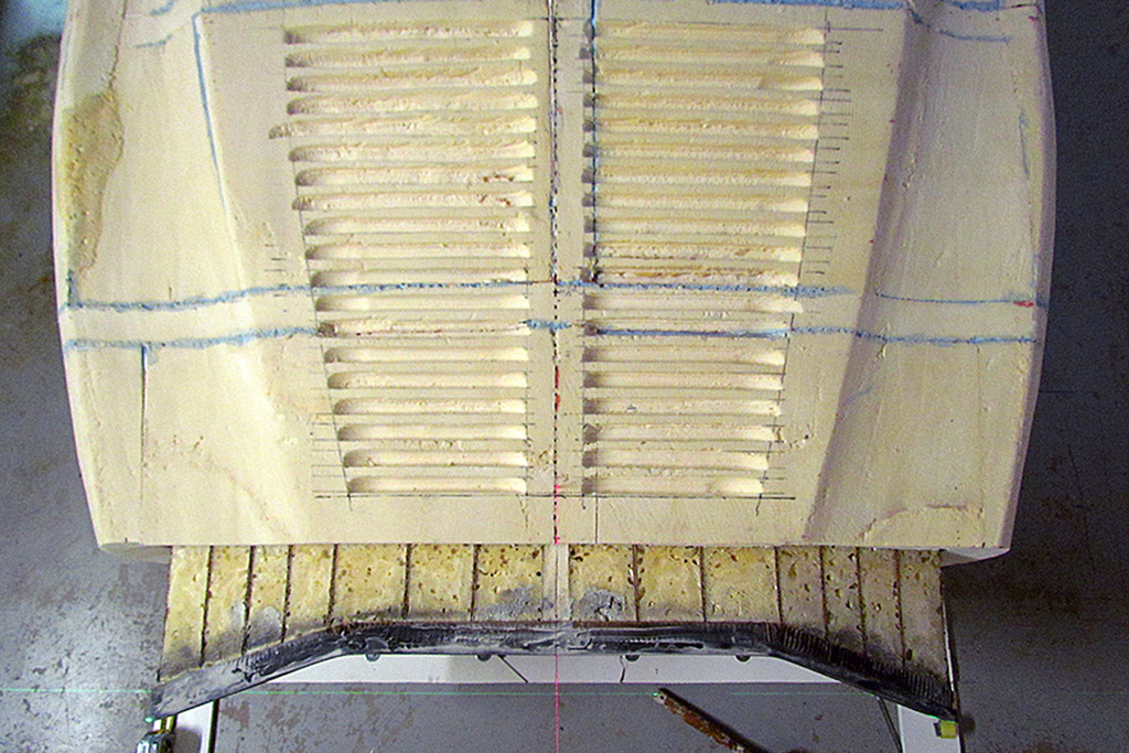
3rd ROW - Rebuilding the Tail
(L) I began by adding foam for the top surface. The setup was to keep the foam in place while the gap foam set.
(CL) I roughed out the top. Then came the sides. They had to be built up of multiple pieces because of the change in shape on the sides.
(CR) Here is one side somewhat roughed out.
(R) And then came the underside. And how it looks reshaped.
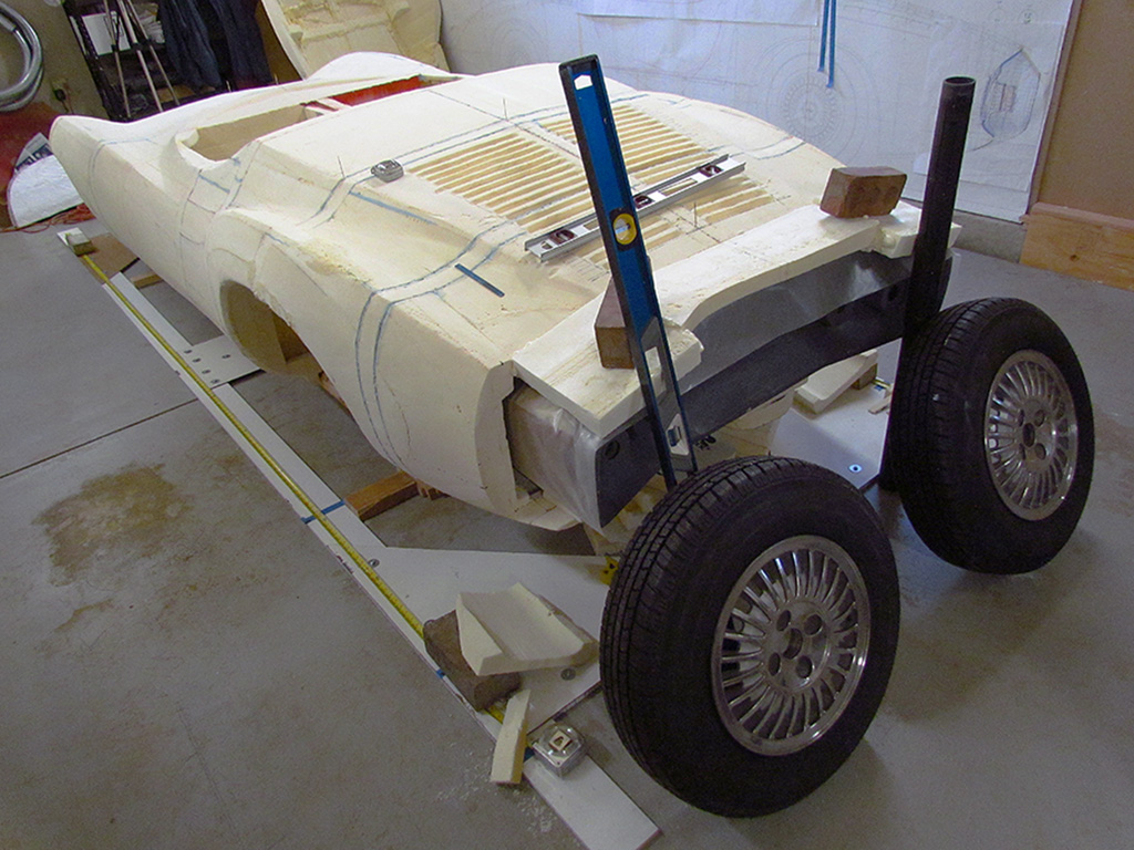
4th ROW - Alignment Check
(L) Another overall view, closely matching my standard 3/4 rear view.
(R) Another view, more straight on to judge where the laser lines fall on the cove.
5th ROW
(L) More alignment checks. Note how the body centerline red and green lasers meet up at the rear toothpick!
(C) A tail-on view.
(R) Off to the side to show the cove concave curvature.